In this Topic Show
This tutorial explains how to create the machining program for the Mill Express demonstration file. The process includes creating facing geometry that is used to create the stock and a facing operation. The outside of the model is then roughed and finished with profile operations. Next, the pocket is roughed, finished, and a chamfer operation is applied to break the top edge. Finally the holes are drilled before simulating the program to confirm the results.
This tutorial highlights the following functionality of the BobCAD-CAM software:
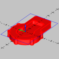
The first step is to open the finished Mill Express CAD model from the Demo Files folder, and then use Save As to rename the file. It is good practice to properly name your files and save them often.
1 In the File menu, click Open.
2 Navigate to C:\BobCAD-CAM Data\BobCAD-CAM V29\Examples\Demo Files, and select Mill Express CAD.bbcd.
3 Click Open.
4 In the File menu, click Save As.
Select or create a new folder to save to, or just use the Demo Files folder.
5 Change the File Name to Mill Express CAM, and click Save.
Before creating our milling job, we create a rectangle that represents our stock boundary which is also the geometry for a facing operation. We then use this rectangle in the Stock Wizard as an alternative way to offset the stock size.
1 Right-click
in the ![]() Layers Manager,
and click Add New Layer.
Layers Manager,
and click Add New Layer.
2 To name the layer, type Facing, and press Enter to finish.
3 Next
to Facing, click ![]() .
.
The icon changes to ![]() to indicate that this is the active layer.
to indicate that this is the active layer.
1 In the Other menu, click Rectangle.
2 Update
the ![]() Data Entry
parameters:
Data Entry
parameters:
Length (X) = 6.500
Width (Y) = 4.250
Select Sharp Corners.
Under Origin:
Select Center.
X = 0.875
Y = 0.000
Z = 0.000
Click OK to create the rectangle.
3 Click Cancel.
4 Press Ctrl+7 to select the ISO 2 view.
The process of creating a CAM Job in BobCAD-CAM includes selecting the type of job and machine. You can then go directly to defining the stock geometry.
1 To create a new CAM Job, do one of the following:
In the Modules menu, click New CAM Job.
In the ![]() CAM Tree, right-click
CAM Tree, right-click ![]() CAM
Defaults, and click New
Job.
CAM
Defaults, and click New
Job.
2 Under Job Type, select Milling.
3 Under Machine, select BC_3X_Mill.
4 Click Stock Wizard.
When you start the stock wizard from the Machining Job dialog box, the Workpiece dialog box displays before the stock wizard. This is used to assign the geometry that we want to use as the workpiece when we simulate the program.
1 Under Define Workpiece, click Pick Solid Model.
2 Click to select the model in the Workspace.
3 Click
![]() to confirm the selection.
to confirm the selection.
4 Click
 to go to the Stock Wizard.
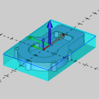
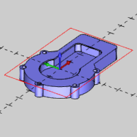
The Stock Wizard is a powerful stock creation tool which can automatically detect geometry in the Workspace to speed up stock creation.
1 Under
Stock Type, with Rectangular
selected, click .
The default setting, Auto from Workspace, automatically creates stock geometry based on the CAD model. (With both wireframe and a solid in the Workspace, Auto from Workspace detects the solid.)
We could use the Offset parameters to increase the size of the automatically created stock, but for this example we pick the rectangle and then adjust only one parameter.
2 Under Geometry Options, click Pick, and then click Pick Geometry.
Press and hold Shift, and click the rectangle to select the entire chain.

Click ![]() to confirm the selection.
to confirm the selection.
3 Now we add stock above the top face of the model that is removed by a facing operation.
Under Offset, change the +Z value to 0.100. (Press Tab to update the stock preview.)
4 Click
.
The Machine Setup is an important part of creating CAM Jobs in BobCAD-CAM. This includes setting the work offset number, clearance plane, and machining origin for each setup that you need on the physical machine.
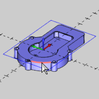
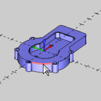
1 In the Machine Setup under Origin, click Origin.
Select the machining origin at the top corner of the stock.
NOTE: This step defines the machining origin (work offset) location for the machining features that you create. The machining origin is independent of the CAD origin, and should be placed in the same location as the work offset location on the physical machine.
2 Click Work Offset. We use the default Work Offset # 1 (G54).
Notice the XYZ values. These are important to create proper simulation when using Machine Simulation Pro. These values shift the part location on the virtual machine (distance from virtual machine zero, which is the center of the top face of the table, to the Machine Setup location).
Update the values:
X = -3.250
Y = -2.125
Z = 3.000
Click OK.
3 Use the default Clearance Plane value of 1.000, and click OK.
The Milling Job is created with the defined stock and machine setup information.
4 In the File menu, click Save.
Selecting the appropriate stock material for the job determines the values used for automatic speeds and feeds calculations in the Milling Wizard. This information can be customized using the Stock Material Library.
1 In
the ![]() CAM Tree, right-click the current
CAM Tree, right-click the current ![]() Stock
Material, and click Edit.
Stock
Material, and click Edit.
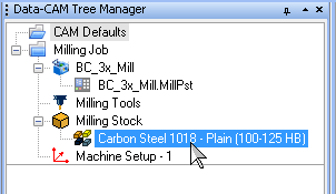
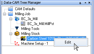
2 Under Material Group, select Aluminum.
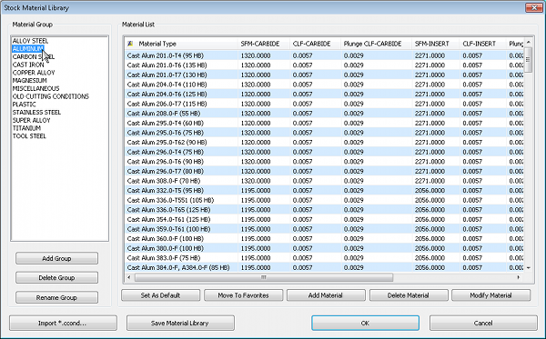
3 In the Material List, click Material Type to sort the list, and select Wrought Alum 6061-0, and click OK.
To begin creating our machining program, we create a 2 Axis feature with a single facing operation.
IMPORTANT: In this tutorial, we use many of the default settings and only update them as needed. If you want more information about particular settings, view the BobCAD-CAM Help System.
1 In
the CAM Tree, right-click ![]() Stock, and click Blank.
Stock, and click Blank.
1 Right-click
![]() Machine Setup,
and click Mill 2 Axis.
Machine Setup,
and click Mill 2 Axis.
2 Click Select Geometry.
Hold Shift, and click the rectangle to select the entire chain.
3 Right-click anywhere in the Workspace, and click OK.
4 Click Next>>.
In this step, we use the model to select the Total Depth. Note that we don't select the Top of Feature, because it is already properly set to 0.000.
1 Next to Total Depth, click Pick Bottom.
2 Click the surface edge on the top of the model.
Notice that the Total Depth is automatically updated from the selection (0.100).
3 Click Next>>.
1 Under Template, click Facing.
Notice that selecting this operation template adds a single Facing operation to the Current Operations list.
2 Click Next>> twice to go to the Posting settings (we are not defining tabs).
1 Notice that Work Offset #1 (G54) is automatically selected as we defined in the Machine Setup.
2 Click Next>>.
1 Under Tool Data, change the Diameter to 2.000, and press Tab.
Notice that the 2 inch face mill is automatically pulled from the Tool Library because the System Tool check box is selected.
2 Click Next>>.
1 Under Patterns, change the Distance value to 0.125.
For the Parameters and Leads settings, we use the default values.
2 In the tree on the left, click Links.
3 Under Link, click Arc to create a smooth transition between each pass of the operation.
1 At the bottom of the Mill 2 Axis Wizard, click Compute.
2 Press Ctrl+S to save the file.
Next we hide geometry that we don't need and explore how the CAM Tree visibility options can make viewing of toolpath easier. These steps are especially helpful as the number of operations in the program increases.
1 In
the Layers Manager next to Solids, click ![]() to set it as the active layer.
to set it as the active layer.
2 Next
to Facing, click ![]() to hide the layer, because
we are done with our facing geometry.
to hide the layer, because
we are done with our facing geometry.
We modified the layers to make it easier to view the computed toolpath.
3 In
the CAM Tree, right-click ![]() Feature 2 Axis, and click Blank/Unblank Toolpath.
Feature 2 Axis, and click Blank/Unblank Toolpath.
This hides the toolpath for all operations in the feature.
4 Under
![]() Feature 2 Axis, click Facing.
Feature 2 Axis, click Facing.
5 The hidden toolpath displays in the Workspace until you click another tree item.
TIP: All feature items in the tree (Feature, Geometry, and Start Point) as well as the operation items highlight the corresponding feature information in the Workspace when you click them.
6 Next
to ![]() Feature 2 Axis,
click
Feature 2 Axis,
click  to collapse the feature.
This is helpful to reduce the need for scrolling through the CAM Tree as the number of features increases.
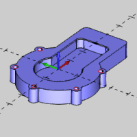
The next feature that we create roughs and then finishes the outside of the model with two profile operations.
1 Right-click
![]() Machine Setup,
and click Mill 2 Axis.
Machine Setup,
and click Mill 2 Axis.
2 Click Select Geometry.
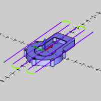
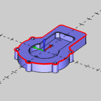
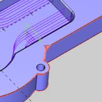
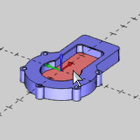
Right-click the outer surface edge of the model, and click Constant Z.
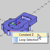
The software selects a chain around the entire model at a constant Z-axis value.
Click ![]() to confirm the selection and return to the wizard.
to confirm the selection and return to the wizard.
3 Click Next>>.
In this step, we use the Pick options to update the Top of Feature and Total Depth. Selecting the Top of Feature allows us to eliminate air cutting (to remove the toolpath from the area the facing operation has already cut).
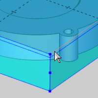
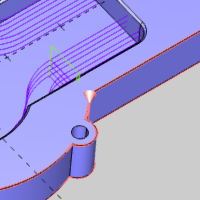
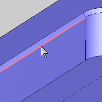
1 Next to Top of Feature, click Pick Top.
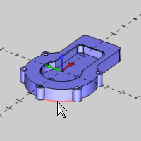
Click the upper surface edge of the model.
The Top of Feature value is updated from our selection (-0.100).
2 Next to Total Depth, click Pick Bottom.
Click the lower surface edge of the model.
The Total Depth value is updated to 0.750.
TIP: When using both Pick Top and Pick Bottom, generally, you should use Pick Top first and then use Pick Bottom to properly set the depth for the feature.
3 Click Next>>.
1 The default operation template, Profiling, contains one Profile Rough operation and one Profile Finish operation as shown in the Current Operations list. This is the appropriate template for this feature.
1 In
the tree under ![]() Profile
Rough, click
Profile
Rough, click![]() Rough.
Rough.
2 Click Tool Crib.
3 Under Tool Category, click Endmill Rough, and click Add From Tool Library.
4 Click the column name Diameter to sort the tool list.
Select the 0.500 inch diameter flat endmill with the 1.125 inch flute length (Tool Label: 1/2 Flat Rough Endmill - Standard).
Click OK.
5 Click OK in the Tool Crib.
All Tool Data is automatically updated with the information from the Tool Library.
6 Click Next>>.
1 Under Patterns, click Side Roughing.
Change the Stock Remaining value to 1.000.
Change the Number of Passes to 3.
2 Click Next>>.
1 We are using the default Side Allowance of 0.015 to leave material for the finishing operation.
2 Under Depth, click Multiple Steps.
In the Depth of Cut box, type 0.750/6, and press Tab. The software calculates the value (0.125).
3 For the remaining operation pages, Leads, Corner types, and Machine Sequence, we use the default settings.
1 Under
![]() Profile Finish, click
Profile Finish, click![]() Finish.
Finish.
2 Click Tool Crib.
3 Under Tool Category, click Endmill Finish, and click Add From Tool Library.
4 Click the column name Diameter to sort the tool list.
Select the 0.125 inch diameter flat endmill with the 1.000 inch flute length (Tool Label: 1/8 Flat Endmill - Long).
Click OK.
5 Click OK in the Tool Crib.
1 Under
![]() Profile Finish, click Leads.
Profile Finish, click Leads.
2 Under Lead-in, click Circular.
Notice that the Lead-out is automatically set to use the same settings because Same as Lead-in is selected.
3 Under Lead-out, change the Overlap Amount to 0.050.
This helps to remove any scallop that may be created by leading in and out from the same location.
4 For this operation, no changes are needed for the Corner Types or Machine Sequence.
1 Click Compute.
Notice that the toolpath calculated inside of the model. This is easily resolved next by modifying the start point.
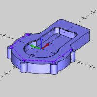
Understanding how to set the start point is an important part of creating 2 Axis features.
1 In
the CAM Tree under ![]() Feature
2 Axis, click Default Chain Start
Point.
Feature
2 Axis, click Default Chain Start
Point.
This highlights the chain in the Workspace. The start point shows that the chain is counterclockwise, and the default compensation is System Compensation Left.
There are two options to update the start point. You can simply reverse the direction, or you can also modify the start point to any location.
2 Right-click Default Chain Start Point, and click Reverse Direction.
We can now compute the toolpath to correct it, but let's first move the start point to a better location.
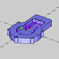
3 Right-click Default Chain Start Point, and click Modify.
Click near the center of the surface edge as shown next.

TIP: While modifying the start point, you can just click near the start point (small cone) to reverse the direction.
4 Click
![]() to confirm the selection.
to confirm the selection.
5 Right-click
![]() Feature 2 Axis, and click Compute All Toolpath.
Feature 2 Axis, and click Compute All Toolpath.
6 Right-click
![]() Feature 2 Axis, and click Blank/Unblank Toolpath.
Feature 2 Axis, and click Blank/Unblank Toolpath.
You can click each operation in the CAM Tree to display only that toolpath in the Workspace.
7 Click
to collapse the second feature.
Save the file.
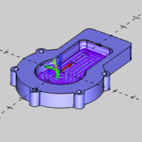
The final 2 Axis feature is created to rough and finish the pocket and to cut a chamfer. This is a special case for 2-axis features as BobCAD-CAM allows you to define the chamfer depth separately from the other operations in the feature, which eliminates the need for an extra feature.
1 Right-click Machine Setup, and click Mill 2 Axis.
2 Click Select Geometry.
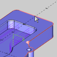
Click to select the bottom face of the pocket,
and click ![]() .
.
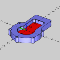
The software automatically extracts the edges of the selected surface to use for the feature.
3 Click Next>>.
1 Click Pick Top.
Click the upper surface edge of the model.
2 Click Pick Bottom.
Click any edge at the bottom of the pocket.
The Total Depth value is updated to 0.500.
3 Click Next>>.
1 Under Template, select Pocketing.
2 Under Current Operations, click Profile Finish to select the insert location. (We are adding an operation below this operation.)
3 Under
Available Operations, click Chamfer Mill, and click ![]() to add the operation to
the Current Operations list.
to add the operation to
the Current Operations list.
4 Click Next>> to update the tree with the new operations.
1 Under
![]() Pocket, click Rough.
Pocket, click Rough.
2 Click Tool Crib.
3 Under Tool Category, click Endmill Rough, and click Add From Tool Library.
4 Click the column name Diameter to sort the tool list.
Select the 0.375 inch diameter flat endmill with the 0.875 inch flute length (Tool Label: 3/8 Flat Endmill - Standard).
Click OK.
5 Click OK in the Tool Crib.
1 Under
![]() Pocket, click Parameters.
Pocket, click Parameters.
2 Under Depth, click Multiple Steps.
Update the Depth of Cut value to 0.200, and press Tab. (Notice that the software automatically calculates the value to create Even Depths of 0.1667.)
3 Click Next>>.
1 Select Ramp, and use the default Ramp Length and Angle of Approach values.
1 Under Profile Finish, click Finish.
2 Notice that the software automatically selected the previous finishing tool from the Tool Crib (1/8 Flat Endmill - Long).
1 Under Profile Finish, click Leads.
2 Under Lead-in, select Circular.
3 Under Lead-out, change the Overlap Amount to 0.050.
1 Under Chamfer Mill, click Chamfer Mill.
2 Click Tool Crib.
3 Click Add From Tool Library.
4 Click the 0.250 inch diameter chamfer endmill (Tool Label: 1/4" Chamfer Endmill).
5 Click OK.
6 Click OK in the Tool Crib.
IMPORTANT: For 2 Axis features, the Total Depth from the Feature settings is not applied to Chamfer operations (or Corner Rounding). These operation types have their own Depth in the operation Parameters. This is done to allow you to use these operations without the need to create a separate feature.
1 Under Chamfer Mill, click Parameters.
2 Under Depth, click Pick Bottom.
Click the lower surface edge of the chamfer.
3 The Depth is updated to 0.0354.
4 Click Next>>.
1 Under Lead-in, select Circular.
2 Under Lead-out, change the Overlap Amount to 0.050.
1 Click Compute.
2 Hide the toolpath and collapse the feature.
1 Right-click Machine Setup, and click Mill Drill Hole.
2 Click Select Geometry.
3 In
the Layers Manager, next to Holes, click ![]() to show the layer.
to show the layer.
4 In the Edit menu, point to Select Entities, and click Pick by Layer.
In the Select Layer dialog box, click Holes, and click OK.
5 Under Point and Arc Usage, click Use as Top.
This setting allows the software to automatically set our Top of Feature value in the wizard based on our selection.
6 Click
![]() to confirm the selection.
to confirm the selection.
The Hole Diameter is automatically set for the selected holes.
7 Click Next>>.
After selecting our geometry, the software automatically groups all the holes into a single hole group. All holes in a hole group share the same Top of Feature and Feature Depth. Our Top of Feature is already set, so next we select our depth for the hole group (we selected wireframe geometry as the top).
1 Under Hole Groups, click Pick Bottom.
Click the lower surface edge of the model.
Under Parameters, notice the Hole Type is set to Through Hole. We use this setting because the holes go completely through the model and this changes the depth calculation accordingly.
2 Click Next>>.
1 Under Template, select Hole.
This operation template adds one Center Drill and one Drill operation to the Current Operations list.
2 Click Next>> to update the tree with the new operations.
1 Click Next>> to go to the Center Drill tool settings.
2 Notice that System Tool is selected which automatically picks an appropriate tool from the Tool Library (after searching the Tool Crib).
3 We use the default Center Drill Parameters, and we use System Tool again for the Drill operation.
4 In the tree under Drill, click Parameters.
5 Under Cycle Type, click Peck.
1 Click Compute.
2 Press T to turn on the transparent view and make it easier to view the toolpath. (Press T again to turn off the transparent view.)
3 In
the Layers Manager, click ![]() to hide the Holes
layer.
to hide the Holes
layer.
4 Right-click Machine Setup, and click Blank/Unblank Toolpath.
Repeat step 4 to show all toolpath.
Now that we have finished creating CAM features, the next step is to simulate the program to check for any necessary changes.
1 Right-click
![]() Milling Job,
and click Simulation.
Milling Job,
and click Simulation.
2 In
the Simulation group on the Simulation tab, click the  Machine button so that it changes
to
Machine button so that it changes
to  Workpiece/Stock
focus.
Workpiece/Stock
focus.
3 In
the Visibility group, click the  Toolpath button to hide the toolpath.
4 Click
 to run the simulation, and adjust the
  speed slider
as needed.
speed slider
as needed.
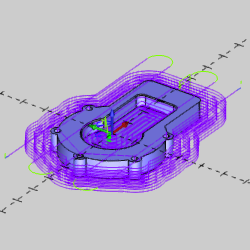
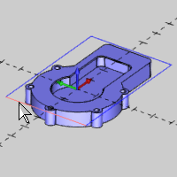
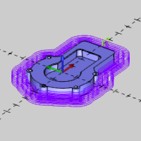
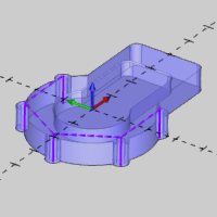
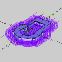
This image shows the final stock model (with the workpiece hidden) and the Tool Number Stock Analysis color scheme.
5 Click
 to close the simulation.
No further changes are needed for the machining program.
6 Save the file.
Congratulations! You have completed the CAM portion of the Mill Express demonstration file.
To learn more about simulation, view Getting Started with Simulation.