Mill 3 Axis Pro CAD Tutorial
Introduction
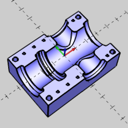
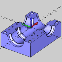
This topic explains how to create the CAD model for the Mill 3 Axis Pro demonstration file. The design process includes first creating a model with solid primitives and then subtracting it from a cube to create the cavity. Finally, the drill holes are created with extruded cuts.
This tutorial highlights the following functionality of the BobCAD-CAM software:
- Utilizing UCS planes for CAD creation
- Creating solid primitives
- Utilizing the Snap Increment to get exact values during sketching
- Creating wireframe geometry
- Using Extrude Boss
- Using Solid Subtract
- Using Solid Fillet
- Creating Hole Patterns
- Using Extrude Cut
Part 1) Open the Template File and Save As
A template file is provided so that you can have the same system colors as shown in this tutorial. We start by opening the template file and renaming it to keep the original file unchanged. It is good practice to always begin a file by saving it with an appropriate name and location and then saving often.
- In the Quick Access Toolbar, at the top left of the application, click
 Open an existing document.
- Navigate to C:\BobCAD-CAM Data\BobCAD-CAM V31\Examples\Demo Files, and select Getting Started Template.bbcd.
- Click Open.
- In the Quick Access Toolbar, click
 Save As.
- Select or create a new folder to save to, or just use the Demo Files folder.
- In the File Name box, type Mill3XP CAD, and click Save.
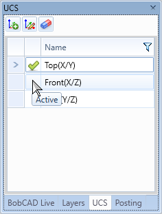
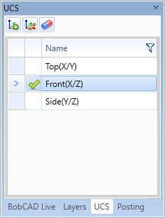
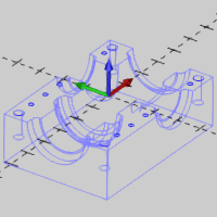
Part 2) Set the Active User Coordinate System (UCS)
The first cylinder is created along the X-axis, and we utilize the Side UCS to easily create the cylinder in the desired orientation.
- In the UCS Manager, click Side (Y/Z) to make it the active coordinate system.
- In the Document Toolbar, click the down arrow next to the
 icon, and click
  ISO1.
ISO1.
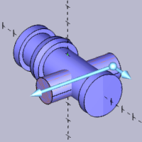
Part 3) Create Cylinders
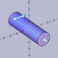
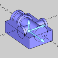
Now we create three cylinders to start defining the initial solid model.
- In the Primitives group, of the Create 3D ribbon, click
 Cylinder.
- Set the Data Entry parameters as follows:
Radius = 1.000
Height = 6.500
In the Start Point group, set the coordinates to the following values:
X = 0.000
Y = 0.000
Z = -3.250
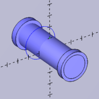
- To create the first cylinder, click OK.
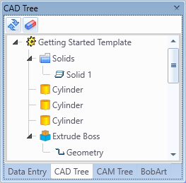
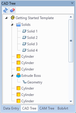
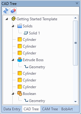
The cylinder is created, and an Cylinder feature is added to the CAD Tree.
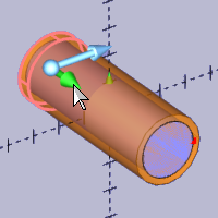
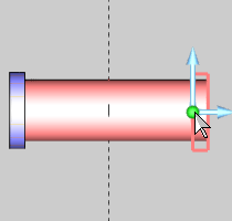
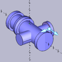
- Click the radius sketch handle and move it outward to increase the radius of the next cylinder.
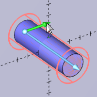
Watch the Radius value in the Data Entry Manager change as you move the sketch handle. You can see that the snap increment is active, because the Radius value updates using the current snap increment value. The snap increment allows us to get the exact value during sketching, thus reducing data entry modifications.
- Click to anchor the sketch handle when the Radius value is 1.250.
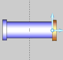
- Now, repeat this process to decrease the height of the cylinder.
Click to anchor the sketch handle when the Height value becomes 0.5000.
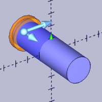
- Click OK.
Another cylinder is created, and another Cylinder feature is added to the CAD Tree.
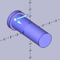
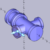
- Click anywhere in the graphics area, to give it key focus, and press Ctrl+1 to select the Top View. This can also be accessed in the document toolbar.
- Use the origin handle to roughly place the next cylinder.
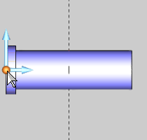
- Ensure the parameters in the Data Entry Manager are as follows:
X = 0.000
Y = 0.000
Z = 2.750
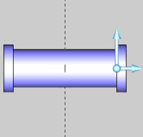
- Click OK.
A third cylinder is created, and another Cylinder feature is added to the CAD Tree.
- Click Cancel.
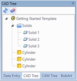
Notice that there are three Solid items in the  Solids folder of the CAD Tree. You can click each Solid item to highlight the solid in the graphics area.
- Press Ctrl+S to save the file.
Part 4) Create a New CAD Layer
Using layers is a great way to keep your CAD files organized. One successful method is to place wireframe geometry on one layer and solid geometry on another layer. This is helpful for hiding, showing, and selecting geometry.
- Click on the Layers tab to show the Layer Manager.
- In the quick selection toolbar of the Layer Manager, click the
 icon to add a new layer.
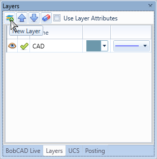
A new layer, Layer-1, is created.
It is automatically set as the active layer, and the name is highlighted to allow for edits.
- To name the layer, type Wireframe.
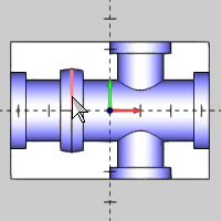
Part 5) Create an Arc
Next we create an arc that is extruded to create a tapered boss in the center of the part.
- In the document toolbar, click the arrow next to the icon to see the view options, and select (ISO 1).
- In the Entity group, of the Create 2D ribbon, click
 Arc.
Arc.
The Arc Creation Options launch in the Data Entry Manager with Arc Center set as the default Creation Option.
- Update the Data Entry parameters:
In the Center group:
X = 0.000
Y = 0.000
Z = -1.250
In the Dimensions group:
Radius = 1.375
- Click OK.
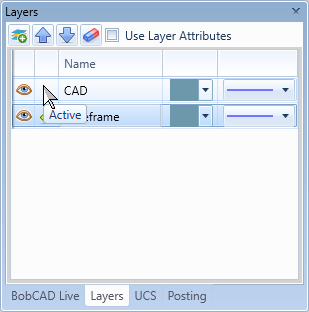
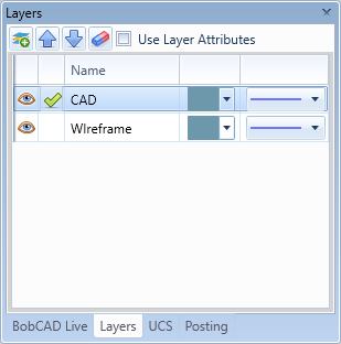
- In the Layers Manager, click in the CAD row of the active column to set it as the active layer.
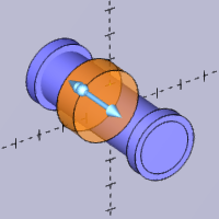
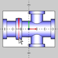
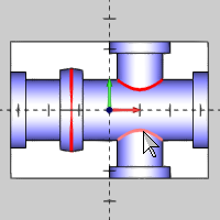
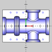
Part 6) Create an Extrude Boss
In this part, we extrude the arc to create a tapered boss, which also merges the intersecting solids into a single solid body.
- In the Extrude group, of the Create 3D ribbon, click
 Extrude Boss.
- Click the arc to select it.
The CAD preview displays.
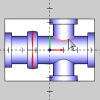
- Update the parameters as follows:
In the Positive Direction group:
Distance = 0.375
Draft Angle = 10.000
In the Other Direction group:
Distance = 0.375
Draft Angle = 10.000
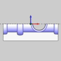
- Click OK.
- Click Cancel.
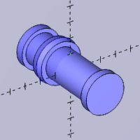
Notice that the Solids folder now contains only one Solid item.
The Extrude Boss function merges all intersecting solids into a single solid body.
- In the Wireframe row of the Layers Manager, click the
 icon to hide the Wireframe layer.
- Press Ctrl+S to save the file.
Part 7) Change the Active UCS
We create the next set of solid primitives using the front plane.
- In the UCS Manager, click Front (X/Z) to make that the active coordinate system.
Part 8) Create Cylinders
Now we create the final three cylinders for the initial solid model.
- In the Primitives group, of the Create 3D ribbon, click Cylinder.
- Update the parameters as follows:
In the Parameters group:
Radius = 0.750
Height = 4.500
In the Start Point group:
X = 1.000
Y = 0.000
Z = -2.250
- Click OK.
The cylinder is created in the Front plane, and another Cylinder feature is added to the CAD Tree.
- Update the parameters as follows:
In the Parameters group:
Radius = 1.000
Height = 0.375
In the Start Point group, the same values are used:
X = 1.000
Y = 0.000
Z = -2.250
- Click OK.
Another cylinder is created, and another Cylinder feature is added to the CAD Tree.
- Update the parameters as follows:
In the Parameters group, the same values are used:
Radius = 1.000
Height = 0.375
In the Start Point group, update the values to the following:
X = 1.000
Y = 0.000
Z = 1.875
- Click OK.
The final cylinder is created, and the last Cylinder feature is added to the CAD Tree.
- Click Cancel.
Notice that there are now four Solid items in the Solids folder.
- Save the file.
Part 9) Add Solid Bodies
In this part, we add the four separate solids to make a single solid body. This part finalizes the initial solid model so it can be used with solid subtract to create the cavity.
- In the Solid Boolean group, of the Create 3D ribbon, click the
 Boolean icon.
Verify the Type is set to Add.
- Click the longest cylinder first (the solid created with Extrude Boss).
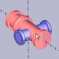
- Select the last three cylinders to add them to the list.
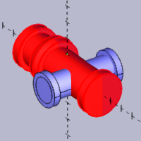
- Click OK.
The solid updates, and the Boolean feature is added to the CAD Tree.
Check the Solids folder and notice that we now have one Solid body.
- Click Cancel.
Part 10) Change the UCS
- In the UCS Manager, click Top (X/Y) to set it as the active coordinate system.
Part 11) Create a Cube
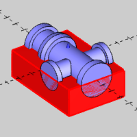
Now we create a cube from which our initial solid model is subtracted.
- In the Primitives group, of the Create 3D ribbon, click
 Cube.
Cube.
- Update the parameters as follows:
In the Parameters group:
Length = 6.500
Width = 4.500
Height = 2.000
In the Start Point group:
X = 0.000
Y = 0.000
Z = -1.000
- Click OK.
- Click Cancel and save the file.
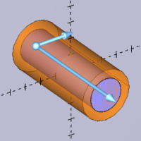
Part 12) Subtract Solid Bodies
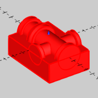
In this part, we subtract the initial solid model from the cube to create the cavity.
- In the Solid Boolean group, of the Create 3D ribbon, click the Boolean icon.
- Set the Type to Subtract.
- Click the cube.
The Cube is added to the Main Solid/Surface Body list, and the focus is shifted to the Solid/Surface Bodies to Subtract list.
- Click the other solid.
The Solid is added to the Solid/Surface Bodies to Subtract list.
Tip: Once there has been at least one solid body added to each list, you can select the Show Preview button to see a preview of the result prior to finalizing the function with the OK button.
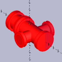
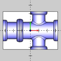
- Click OK.
The solid updates, and the Boolean feature is added to the CAD Tree.
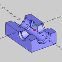
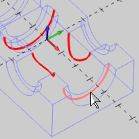
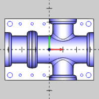
Part 13) Create Solid Fillets
In this part, we apply fillets to the surface edges of the cavity. Note that these steps show you how to create different size fillets at the same time (which results in a single feature).
- In the Corners group, of the Create 3D ribbon, click
 Solid Fillet.
- Press Ctrl+1 to switch to the Top View.
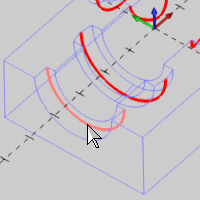
- With the default Radius of 0.250 select the four edges as shown next.
- Double-click in the Radius box, and type 3/16.
- Press Tab and notice that the value is automatically calculated.
- Click in the graphics area to give it focus, and press S to turn off the Shaded view. Alternatively, in the document toolbar, click
 Shaded.
Tip: Turning off the Shaded view is not required to make the following selections, but there are many benefits, for all types of selections, that come from utilizing the Shaded view.
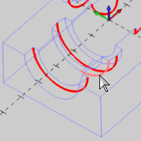
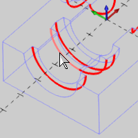
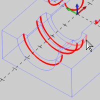
- Select the surface edges as shown next. (There are eight selections.)
Rotate the view as needed, and be sure to select the edges at the bottom of the cut outs, not the top.
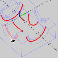
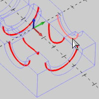
Rotate the model if needed to select the edges on the opposite side of the model.
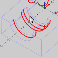
- Click OK.
The solid updates, and a Solid Fillet feature is added to the CAD Tree.
- Click in the graphics area to give it focus, and press S.
- Save the file.
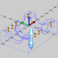
Part 14) Create Hole Patterns
The last remaining features for the model are the holes. As an easy way to create a grid of holes, instead of drawing them individually, we utilize hole patterns.
- Press Ctrl+1 to select the Top view.
- In the Pattern group, of the Create 2D ribbon, click
 Hole Pattern.
- Update the parameters as follows:
In the Pattern Parameters group:
Select the Grid option
Width = 1.750
Height = 3.750
In the Hole Parameters group / Number of Holes:
X = 3
Y = 2
In the Hole Parameters group / Hole Diameter:
Hole Diameter = 0.1875
Select the Break Arc check box.
In the Origin group:
X = -2.125
Y = -1.875
Z = 0.000
- Click OK.
- Update the parameters as follows:
In the Pattern Parameters group:
Width = 0.000
In the Hole Parameters group / Number of Holes:
X = 1
Y = 2
In the Origin:
X = 2.375
- Click OK.
- Update the parameters as follows:
In the Pattern Parameters group:
Width = 5.750
In the Hole Parameters group / Number of Holes:
X = 2
Y = 2
Hole Diameter:
Hole Diameter = 0.375
In the Origin group:
X = -2.875
Y = -1.875
Z = 0.000
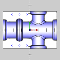
- Click OK.
- Save the file.
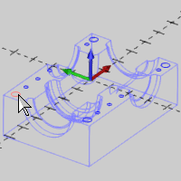
Part 15) Create an Extruded Cut
In this part, we extrude the hole patterns to cut the holes into the model.
- Press Ctrl+7 to select the ISO 2 view.
- In the Extrude group of the Create 3D ribbon, click
 Extrude Cut.
- Update the parameters as follows:
In the Positive Direction group:
Distance = 0.000
Draft Angle = 0.000
In the Other Direction group:
Distance = 1.000
Draft Angle = 0.000
Note: The Positive Direction values can be set to zero or left alone. For this cut they are not important as we are cutting in the negative direction.
- In the Quick Selection group, of the Home ribbon, click the down arrow on
 Pick+Match Layer, and select
  Pick+Match Radius from the drop down.
Using this will select all arcs of matching size when we select an arc. That way, we only need to select one large arc, to have all the rest selected as well.
- Click in the graphics area to give it focus, and press S.
- Click to select any one of the larger circles.
The Preview appears.
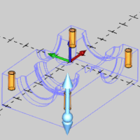
- Click OK.
The solid updates, and an Extrude Cut feature is added to the CAD Tree.
- Under Other Direction, update the Distance to 0.500.
- Click to select any one of the smaller circles.
- Click OK.
The solid updates, and an Extrude Cut feature is added to the CAD Tree.
- Click Cancel.
- Click anywhere in the graphics area, and press S to turn on the Shaded view.
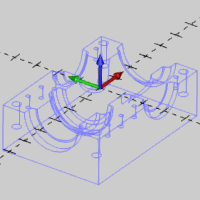
Part 16) Move Hole Patterns to the Wireframe Layer
For the final part of this tutorial, we show you one way to move existing geometry to another CAD layer. This helps to keep our drawing organized as we forgot to create the hole patterns on the Wireframe layer.
- In the Document Toolbar, click
 Select Mode to enter selection mode.
- In the Selection Mask toolbar, in the graphics area, click
 Solid Mask to remove the ability to select solids.
- Drag a window to select all of the geometry.
Only wireframe geometry is selected.
- In the Modify group, of the Home ribbon, click
 Modify Layer.
- In the Select Layer dialog box, click Wireframe.
- Click OK.
- Save the file.
Congratulations! You have finished the Mill 3 Axis Pro CAD model.
Next Topic
To learn how to machine the model, view the Mill 3 Axis Pro CAM Tutorial.