Mill 3 Axis Standard CAD Tutorial
Introduction
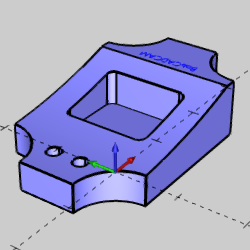
This tutorial explains how to create the CAD model for the Mill 3 Axis Standard demonstration file. The design process includes using the Shape Library and other wireframe functions to create the profile, pocket, and holes for the model. The solid is created by extruding the wireframe geometry with an Extrude Curve. The Extrude Cut is then used for the pocket, holes, and to cut a radius from the solid.
This tutorial highlight the following functionality of the BobCAD-CAM software:
-
Creating wireframe with the Shape Library
-
Creating and managing CAD layers
-
Using Arc Coordinates
-
How to modify entity attributes
-
Utilizing UCS planes for CAD creation
-
Using Extrude Curve
-
Using the Snap Increment to eliminate data entry changes
-
Utilizing CAD layers to aid in geometry selection
-
Using Extrude Cut
-
Creating text
Part 1) Open the Template File and Save As
A template file is provided so that you can have the same system colors as shown in this tutorial. We start by opening the template file and renaming it to keep the original file unchanged. It is good practice to always begin a file by saving it with an appropriate name and location and then saving often.
- In the Quick Access Toolbar, at the top left of the application, click
 Open an existing document.
- Navigate to C:\BobCAD-CAM Data\BobCAD-CAM **Current Version**\Examples\Demo Files, and select Getting Started Template.bbcd.
- Click Open.
- In the Quick Access Toolbar, click
 Save As.
- Select or create a new folder to save to, or just use the Demo Files folder.
- In the File Name box, type Mill 3XS CAD, and click Save.
Part 2) Shape Library
To begin creating geometry, we use the Shape Library to quickly define wireframe for our model.
- In the Shapes group of the Create 2D ribbon, click
 Shape Library.
The Data Entry Manager is populated with the data for the default shape.
- Click the image of the Disk shape in the Data Entry Manager.
A dialog presenting the available shapes appears.
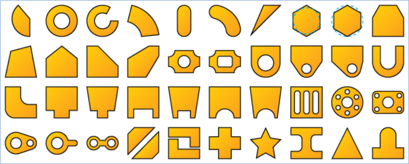
- Select the
 Inverse Fillet Rectangular Hole shape.
- In the Data Entry Manager, update the shape parameters:
- = 4.000
- = 2.500
- = 1.125
- = 1.500
- = 0.750
- = 0.125
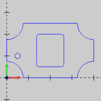
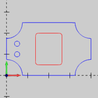
Notice that the CAD preview updates as you enter the parameters. This allows you to confirm the proper result before creating the shape.
- In the Origin group, click the Center to see available options.
- Select Bottom Left.
The preview shifts its position.
- Click OK to create the shape.
The shape is created in the graphics area, and the Shape Library feature is added to the CAD Tree.
- Click Cancel to close the Data Entry Manager.
- Click anywhere in the graphics area, to give it key focus, and press F to activate Fit All.
- Press Ctrl+S to save the file.
Part 3) Create a CAD Layer and Set as Active Layer
Next we create a new CAD layer and set it as the active layer before creating some arcs. CAD layers are a great way to keep your drawings organized and are helpful for hiding, showing, and selecting geometry.
- Right-click anywhere in the Layers Manager, and click Add New Layer.
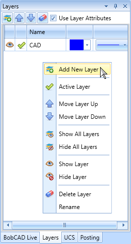
A new layer is created with the name, Layer-1, highlighted to allow for edits, and is set to the active layer automatically.
- To name the layer, type Holes.
The name is automatically updated once focus is placed on another area, or function.
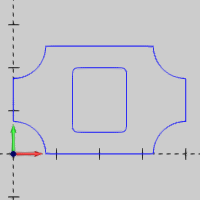
Part 4) Create Arcs
Now we create two arcs that are used to cut the holes in the model later in this tutorial.
- In the Entity group of the Create 2D ribbon, click
 Arc.
Arc.
The Arc Center Creation Option is selected by default.
- Update the Center group parameters:
X = 0.500
Y = 1.000
Z = 0.000
- Update the Dimensions group parameters:
Radius = 0.125
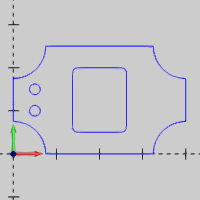
- Click OK to create the first arc.
- Update the Y values in the Center group to 1.500.
- Click OK to create the second arc.
- Click Cancel to close the Data Entry Manager.
Part 5) Create CAD Layers and Modify Attributes
Next we create two more CAD layers to help keep our drawing organized. Then we use Modify Attributes to move existing geometry to one of the layers.
- In the quick access toolbar of the Layers Manager, click the
 New Layer button.
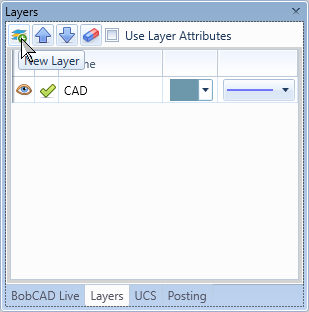
- Type Pocket to name the layer.
- Create another layer and change its name to Solids.
- Right-click on the Pocket layer, and click Hide Layer.
- In the document toolbar, click
 Select Mode to enter selection mode.
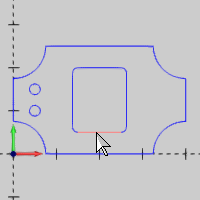
- In the graphics area, press and hold Shift, and click any entity of the inner rectangle to select the entire chain. This is called chain selection.
- In the Modify group of the Home ribbon, select
 Modify Layer.
The Select Layer dialog appears.
- Select Pocket.
- Click OK.
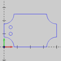
The pocket geometry is no longer visible after moving it to the hidden layer.
- Press Ctrl+S to save the file.
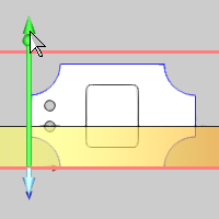
Part 6) Extrude a Wireframe Curve
In this part, we use Extrude Curve to create a solid from our wireframe profile for the model.
- In the Extrude group of the Create 3D ribbon, click
 Extrude Curve.
- Press Ctrl+7 to select the ISO 2 view. Alternatively, in the Document Toolbar, click the
 icon.
icon.
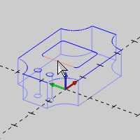
- Chain select the outer profile.
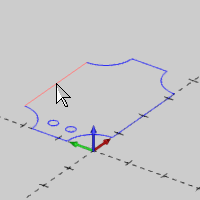
The Preview appears.
- Click the upper sketch handle to activate sketching.
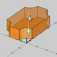
- Move the handle down below the selected profile to change the extrusion direction, and watch the Distance value in the Data Entry Manager under Other Direction.
Notice that the Data Entry parameters automatically update while moving the sketch handle.
Tip: In this step, we are dragging the extrusion preview from the positive direction down into the negative (other) direction. When you reach the geometry, the positive distance becomes zero, and BobCAD-CAM automatically switches from the positive sketch handle to the negative sketch handle to allow you to easily change the extrusion direction.
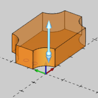
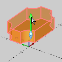
- Move the sketch handle until under Other Direction, the Distance value becomes 1.000, and click to anchor the sketch handle.
Thanks to the snap increment, we can achieve exact values using sketch handles, thus eliminating some data entry modifications.
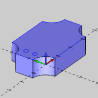
- Click OK to create the solid.
The solid is created in the graphics area, and an Extrude Curve feature is added to the CAD Tree.
Part 7) Extrude Wireframe to Cut the Pocket and Holes
For this part, we use Extrude Cut to create the holes and pocket in the solid model.
Cut the Holes
- In the Extrude group, of the Create 3D ribbon, click
 Extrude Cut.
- In the Quick Selection group, of the Home ribbon, click on the drop down arrow for
 Pick By Layer, and select Pick by Layer.
- Select Holes.
- Click OK.
The Preview appears.
- Set the Distance in the Positive Direction group to 0.000.
Notice the Other Direction is automatically given a value of 1.000.
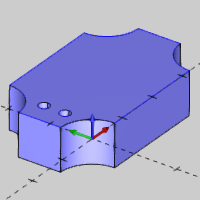
- Click OK to cut the holes.
The solid is updated, and an Extrude Cut feature is added to the CAD Tree.
Tip: You can press T, to turn on the Transparent view, and see that the holes are cut through the entire model. Press T again to turn off the Transparent view.
Tip: This effect could have also been achieved by selecting the holes in Part 6) / Step 3. However, creating the holes as a separate feature allows us to suppress them if needed when we apply toolpath.
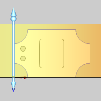
Cut the Pocket
- In the Layer Manager, click in the Pocket row of the Visibility column to show the Pocket layer.
- Click in the graphics area to give it focus, and press S to turn off the shaded view. This is also accessible through the document toolbar.
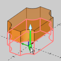
- Chain select the wireframe for the inner pocket.
The Preview appears.
- Press S to turn on the shaded view.
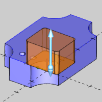
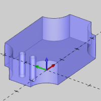
- Under Other Direction, update the Distance value to 0.750. The Preview updates.

- Click OK. The solid is updated, and an Extrude Cut feature is added to the CAD Tree
- Click Cancel.
Hide Layers and Set Active Layer
Now we hide the layers that we are finished using, and set the CAD layer as active before creating more geometry.
- In the Layer Manger, click and drag from the Holes layer, to the Pocket layer to highlight both of them.
- Right-click the one of the highlighted layers, and click Hide.
Both layers are hidden.
- Right-click the CAD layer, and click Active Layer.
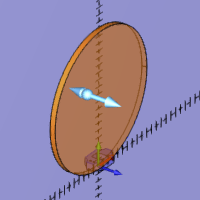
Part 8) Add a Radius to the Model Using Extrude Cut
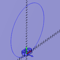
In this part, we create a large circle utilizing the front (X/Z) plane. The circle is then extruded to cut a radius into the top face of the model.
Create an Arc on the Front UCS (User Coordinate System)
- Click on the tab for the UCS Manager.
- In the UCS Manager, click the Front (X/Z) to make that the active UCS.
Geometry is now created using front coordinate system for as long it is the active coordinate system.
- In the Entity group, of the Create 2D ribbon, click Arc.
The Arc Center Creation Option is selected by default.
- Update the Center group parameters:
X = 0.000
Y = 9.000
Z = 0.000
- Update the Dimensions group parameters:
Radius = 9.500
- Click OK to set the arc.
- Click Cancel to close the arc function.
- Click anywhere in the graphics area, and press F to activate Fit All.
Set the Active Layer
Now that the arc has been created on the CAD layer, we need to switch back to the Solids layer to keep our solid on this layer.
- Click on the Layers tab to open the Layers Manager.
- Right-click the Solids layer, and click Active Layer.
Note: When an Extrude Cut or Extrude Boss is used, the solid being affected will move to the active layer. Changing back to the Solids layer, as we have done here, will ensure the solid remains on it's own layer.
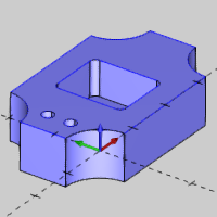
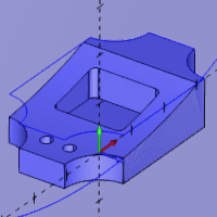
Use Extrude Cut to Create the Radius
- In the Extrude group, of the Create 3D ribbon, click Extrude Cut.
- Click the new arc to select.
The Preview appears.
- Press Ctrl+1 to select the Top view.
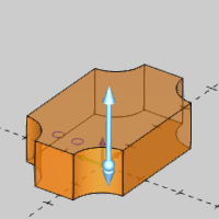
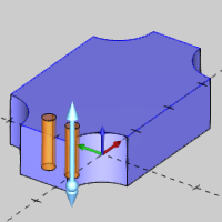
- Use the sketch handle to extend the extrude preview through the entire model.
- Click OK. The solid is updated, and an Extrude Cut feature is added to the CAD Tree
- Click Cancel.
- Press Ctrl+7 to better view the result.
Change the UCS and Manage CAD Layers
- In the UCS Manager, Top (X/Y) to make it the active layer.
- In the Layers Manager, right-click CAD, and click Hide.
- Create a new layer named Text.
Upon creation, this will automatically be the active layer.
Part 9) Create Text
The final part of this tutorial is to create text. This text is used later to machine the name BobCAD-CAM into the model.
- In the Text group. of the Create 2D ribbon, click
 Text.
Text.
- Update the Data Entry parameters:
In the Font group, click BobCAD Font.
Click the down arrow, and select AFNT03.
Click in the text box, and type BobCADCAM.
In the Base Point group, set the values to:
- X = 3.250
- Y = 1.250
- Z = 0.000
In the Base Point group, click the arrow next to Bottom Center, and select Center to adjust the origin of the Text.
In the Parameters group, set the Height to 0.125.
Set the Angle to 90.000.
- Press Ctrl+1 to select the top view, and press F.
- Click OK to finalize the text.
- Click Cancel.
- Set the Solids layer as the active layer, and hide the Text layer.
- Press Ctrl+7 to enter the ISO 2 view.
- Save the file.
Congratulation! You have finished the Mill 3 Axis Standard CAD model.
Next Topic
To learn how to machine the model, view the Mill 3 Axis Standard CAM Tutorial.