Mill Turn Zone Post Blocks
MILL TURN ZONE POST BLOCKS
The BobCAD-CAM posting engine supports 100 Zone Blocks that are used to set output options based on combinations of machine axis components being used together. An example of this would be using the Left Chuck/Spindle with the Upper turret.
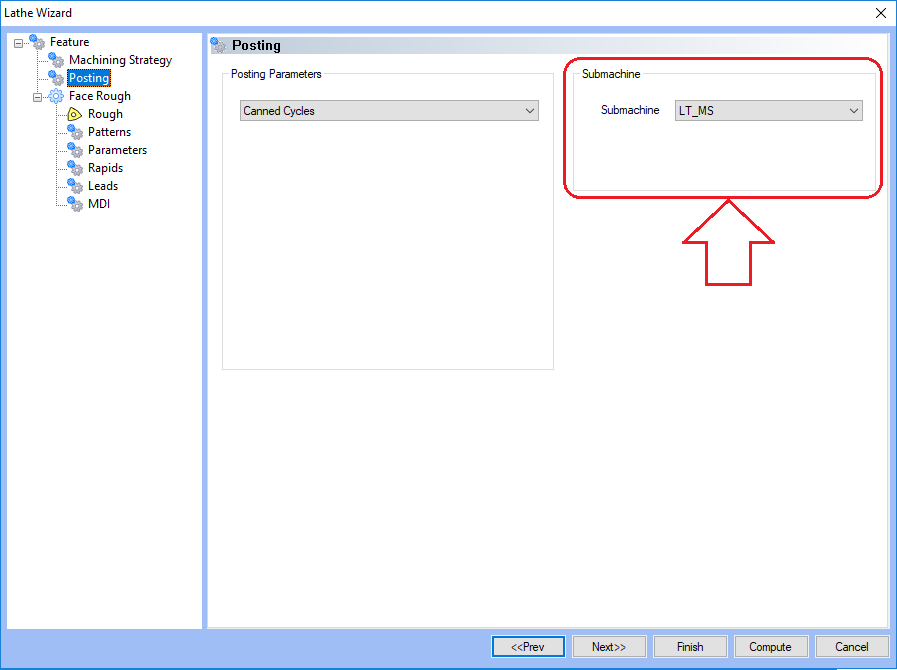
Each machining feature has a Submachine defined on the Posting page of the Feature Wizard as shown below.

This tells the posting engine what Machine Devices to use for output in the NC file for the machining operations.
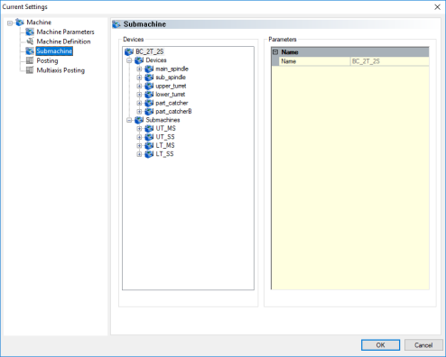
On the Submachine page of the Default Current Settings Dialog you can see the combinations of devices that have been setup into different Submachines.

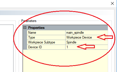
To identify the ID of a device click on the device in the Device section on the Submachine page of the Default Current Settings dialog and you can identify the Type and Device ID.

In the post processor, each Zone is created for combinations of tool and workpiece devices. Looking at Zone 1 you can see that it is defined for Tool Device 1 and Workpiece Device 1.
// Zone 1
6000. Zone 1 (T1 - W1) - Shift - First Linear Axis? 0.000
6001. Zone 1 (T1 - W1) - Shift - Second Linear Axis? 0.000
6002. Zone 1 (T1 - W1) - Shift - Third Linear Axis ? 0.000
6003. Zone 1 (T1 - W1) - Shift - First Rotary Axis? 0.000
6004. Zone 1 (T1 - W1) - Shift - Second Rotary Axis? 0.000
6005. Zone 1 (T1 - W1) - Scale - First Linear Axis? 1.0
6006. Zone 1 (T1 - W1) - Scale - Second Linear Axis? 1.0
6007. Zone 1 (T1 - W1) - Scale - Third Linear Axis ? 1.0
6008. Zone 1 (T1 - W1) - Scale - First Rotary Axis? 1.0
6009. Zone 1 (T1 - W1) - Scale - Second Rotary Axis? 1.0
6010. Zone 1 (T1 - W1) - Prefix for Polar Interpolation C/Y Axis? "C"
6011. Zone 1 (T1 - W1) - Enable Code? "G110 X1 Y1 Z1 C1 (ZONE 1 ENABLE CODE)"
6012. Zone 1 (T1 - W1) - Disable Code? "G111 (ZONE 1 DISABLE CODE)"
6013. Zone 1 Arc Definition? 0
6020. Zone 1 Command Block 1
6021. Zone 1 Command Block 2
6022. Zone 1 Command Block 3
6023. Zone 1 Command Block 4
6024. Zone 1 Command Block 5
Zone Settings
In each zone block there are:
-
Shifts
-
Scales
-
Prefix Definition
-
Enable/Disable Code Definition
-
Arc Definition
-
Zone Command Post Blocks
These settings and Post Blocks are applied only when the zone is active. The following definitions give more details on each section of the zone blocks and what they do.
Shifts& Scales
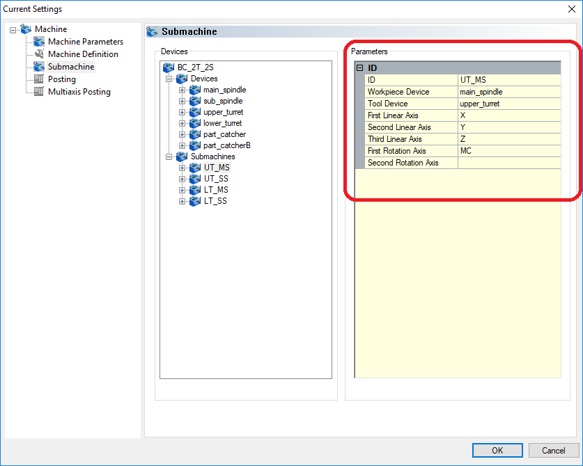
The shift and scale value in each Zone’s blocks are used to shift or scale the output coordinates that are output for the first, second and third linear axes, and the first, and second rotary axes. To determine which axis is the first, second, or third you must look at the definition for the Submachine that is being used in the feature.

NOTE: The value entered will be applied in addition to any global shift and scale values that have been set.
Prefix for Polar Interpolation
This block is used to define the prefix that is to be used for the “Y” axis output during a Polar Interpolation milling cycle.
Enable & Disable Codes
These blocks are used to define codes or commands that need to be output to tell the machine’s controller to enable or disable a zone. These codes are output using the following post variables:
-
zone_device_enable
-
zone_device_disable
The posting engine will output the codes defined for the specific zone that is active for each operation as the NC file is processed.
You can access and output a specific Zone Device’s enable or disable code in any postblock by using the following variables:
-
zone_device_disable_1 thru zone_device_disable_100
-
zone_device_enable_1 thru zone_device_disable_100
Arc Definition
This Post Question allows you to define how the posting engine should output arc motion based on the plane and the combination of axes used. Above the Zone section in the post is a commented table that shows the different combinations of how the posting engine should output the arc moves.
// 6013 - Zone 1 Arc Definition (Applies to all zones)
// Value Lathe G17 G18 G19
// 0 Normal NormalNormalNormal
// 1 Normal NormalNormal Reverse
// 2 Normal Normal Reverse Normal
// 3 Normal Normal Reverse Reverse
// 4 Normal Reverse Normal Normal
// 5 Normal Reverse Normal Reverse
// 6 Normal Reverse Reverse Normal
// 7 Normal Reverse ReverseReverse
// 8 Reverse Normal NormalNormal
// 9 Reverse Normal Normal Reverse
// 10 Reverse Normal Reverse Normal
// 11 Reverse Normal Reverse Reverse
// 12 Reverse Reverse Normal Normal
// 13 Reverse Reverse Normal Reverse
// 14 Reverse ReverseReverse Normal
// 15 Reverse ReverseReverseReverse
Zone Command Blocks
Each zone has 5 Command Blocks that can be used to output custom required code to the NC file when the specific Zone is used. These are called from normal Post Blocks using the following command variables:
-
zone_command_block_1
-
zone_command_block_2
-
zone_command_block_3
-
zone_command_block_4
-
zone_command_block_5
You can call a specific Zone’s Command Block to be called and executed in the post processor using the following:
-
zone_command_block_1_1 thru zone_command_block_1_99
-
zone_command_block_1_1 thru zone_command_block_2_99
-
zone_command_block_1_1 thru zone_command_block_3_99
-
zone_command_block_1_1 thru zone_command_block_4_99
-
zone_command_block_1_1 thru zone_command_block_5_99
Device Blocks
In the Mill Turn post processor the Device blocks are used to define parameters that are specific for each device type. The supported devices are:
-
Workpiece Device
-
Tool Device
-
Tailstock Device
-
Steady Rest Device
-
Parts Catcher Device
Each Device listed has a series of Post Questions used to define how the posting engine should output the NC code, or assign prefixes when that device is used. The devices are identified on the Submachines page of the Default Current Settings > Submachines page.
Workpiece Device Blocks
The Workpiece Device Blocks contain post questions and command blocks to set and define how the posting engine should output code for that specific workpiece.
Enable/Disable - You can define the Enable and Disable strings to be output from the workpiece_device_enable and workpiece_device_disable post variables.
Enable Code? "G15"
Disable Code? "G14"
Spindle Codes – You can define the On Forward, Off, and On Reverse strings to be output from the spindle_on post variable.
Spindle ON Forward Code? "M3"
Spindle OFF Code? "M5"
Break/Clamp Codes – You can define the On, Off, and On Auto codes to be output from the workpiece_device_brake, workpiece_device_brake_on, workpiece_device_auto_brake_on, and workpiece_device_brake_off post variables.
Brake ON Code? "M14 (WORKPIECE BRAKE ON)"
Brake Auto ON Code? "M14 (WORKPIECE AUTO BRAKE ON)"
Brake OFF Code? "M15 (WORKPIECE BRAKE OFF)"
Spindle Gear Range – You can define the gear range codes to be output for up to 10 gear ranges as well as define what speeds indicate the limit for each range. The gear range codes is output using the spindle_gear post variable.
Spindle Gear Range 1 Code? ""
Spindle Gear Range 2 Code? ""
Spindle Gear Range 3 Code? ""
Spindle Gear Range 4 Code? ""
Spindle Gear Range 5 Code? ""
Spindle Gear Range 6 Code? ""
Spindle Gear Range 7 Code? ""
Spindle Gear Range 8 Code? ""
Spindle Gear Range 9 Code? ""
Spindle Gear Range 10 Code? ""
Gear Range 1 Spindle Speed? 500
Gear Range 2 Spindle Speed? 1000
Gear Range 3 Spindle Speed? 1499
Gear Range 4 Spindle Speed? 1999
Gear Range 5 Spindle Speed? 2500
Gear Range 6 Spindle Speed? 2500
Gear Range 7 Spindle Speed? 2500
Gear Range 8 Spindle Speed? 2500
Gear Range 9 Spindle Speed? 2500
C Axis Enable/Disable – You can define the code to be output for enabling and disabling the C axis for this workpiece. These codes are output from the mt_mode, c_axis_enable, and c_axis_disable codes.
C Axis Enable Code? "M154 (ENABLE C AXIS MODE)"
C Axis Disable Code? "M155 (DISABLE C AXIS MODE)"
Rotary Index(Forward/Reverse) – You can define the code to be output for the rotary axis to index in a forward or reverse direction. These codes are output from the workpiece_device_rotary_index_forward_code, workpiece_device_rotary_index_reverse_code, primary_rotary_direction, and secondary_rotary_directionpost variables.
Rotary Index Forward Code? "M14"
Rotary Index Reverse Code? "M15"
Chuck Clamp/Brake – You can define the codes to be output for the rotary clamping/braking for the workpiece device. These codes are output from the chuck_clamp, chuck_unclamp post variables.
Chuck clamp? "M10 (CLAMP CHUCK)"
Chuck unclamp? "M11 (UNCLAMP CHUCK)"
Spindle Sync Codes – You can define the codes to be used for syncing ON/OFF. These codes are output from the spindle_sync, spindle_unsync post variables.
Spindle Sync Code? "G199"
Spindle Unsync Code? "G198"
Workpiece Device Command Blocks – These blocks are postblocks and not post questions. Postlines can be built in these blocks and output using the workpiece_device_command_block_1 thru workpiece_device_command_block_9 post variables.
Workpiece Device 1 Command Block 1
Workpiece Device 1 Command Block 2
Workpiece Device 1 Command Block 3
Workpiece Device 1 Command Block 4
Workpiece Device 1 Command Block 5
Workpiece Device 1 Command Block 6
Workpiece Device 1 Command Block 7
Workpiece Device 1 Command Block 8
Workpiece Device 1 Command Block 9
When the above mentioned post variables are encountered on a postline the posting engine will determine the currently active workpiece device and execute the command block # that is called by the variable.
Calling a specific workpiece device command block can be accomplished by using the post variables:
workpiece_device_command_block_1_1 thru workpiece_device_command_block_10_10
Tool Device Blocks
The Tool Device Blocks contain post questions and command blocks to set and define how the posting engine should output code for that specific tool device.
Enable/Disable - You can define the Enable and Disable strings to be output from the tool_device_enableand tool_device_disable post variables.
Enable Code? ""
Disable Code? ""
Spindle Codes – You can define the On Forward, Off, and On Reverse strings to be output from the live_spindle_on post variable.
Spindle ON Forward Code? "M133"
Spindle OFF Code? "M135"
Spindle ON Reverse Code? “M134”
Break/Clamp Codes – You can define the On, Off, and On Auto codes to be output from the tool_device_brake, tool_device_brake_on, tool_device_auto_brake_on, and tool_device_brake_off post variables.
Brake ON Code? "M14"
Brake Auto ON Code? "M14"
Brake OFF Code? "M15"
Coolant Codes – You can define the codes to be output for different coolant settings for the tool device. These codes are output from the coolant_on, coolant_off post variables.
Coolant 1 ON Code? "M08"
Coolant 2 ON Code? "M08"
Coolant 3 ON Code? "M08"
Coolant 4 ON Code? "M08"
Coolant OFF Code? "M09"
Rotary Index(Forward/Reverse) – You can define the code to be output for the rotary axis to index in a forward or reverse direction. These codes are output from the tool_device_rotary_index_forward_code, tool_device_rotary_index_reverse_codepost variables.
Rotary Index Forward Code? "M14"
Rotary Index Reverse Code? "M15"
Spindle Gear Range – You can define the gear range codes to be output for up to 4 gear ranges as well as define what speeds indicate the limit for each range. The gear range codes are output using the spindle_range post variable.
20020. Spindle Range 1? 300
20021. Spindle Range 2? 800
20022. Spindle Range 3? 1200
20023. Spindle Range 4? 1500
20025. Spindle Range 1 Code? ""
20026. Spindle Range 2 Code? ""
20027. Spindle Range 3 Code? ""
20028. Spindle Range 4 Code? ""
20029. Spindle Range 5 Code? ""
Toolchange Format – The BCPst posting engine supports multiple output formats that are commonly required for mill turn machine tools.
|
Block 20x30 Setting |
T Code Example |
Definition |
Additional Information |
|
1 |
T0001 |
Outputs the Tool number formatted by the number of digits by post question 20x31. |
Existing Option |
|
2 |
T0101 |
Outputs the tool number * 101 and output using the number of digits defined by post question 20x31. |
Existing Option Haas (Fanuc Coordinate Format), Haas (Yasnac Coordinate Format) Mori Seiki NLX 2500Y |
|
3 |
T0102 |
Outputs the (tool number * 100) + the offset value. For example, if the Tool Number is set to 1 and the diameter offset is set to 3, the output is T0103. |
Existing Option Haas (Fanuc Coordinate Format), Haas (Yasnac Coordinate Format) Mori Seiki NLX 2500Y |
|
4 |
T0002 |
Outputs the diameter offset number only using the number of digits defined by post question 20x31. |
Existing Option |
|
5 |
T0201 |
Outputs the (diameter offset number * 100) + the tool number. (Opposite of setting 3). This is the 4 digit format for Okuma. |
Okuma OSP U10L(4 digit) |
|
6 |
T020102 |
Outputs the (Diameter Offset number * 10000) + (tool number * 100) + length offset number. The tool number is made up of 3 pairs of digits. Txxyyzz where xx = Length Offset Number, yy = Tool Number, zz = diameter offset number. |
Okuma OSP U10L(6 digit) |
|
7 |
T0001 |
Outputs the tool number and also triggers the output of the Tool Change Code string defined on post question: 654 thru the toolchange_code variable. The number of digits used for the tool number should be pulled from post question: 20x31. This format is used to support Automatic Tool Changers on B axis spindles. |
Mazak(ATC Systems) |
|
8 |
T001.06 |
Outputs the tool number with a 2 place decimal value. The decimal value is the Suffix Code. This format is used by Mazak ATC systems. This mode also triggers the output of the toolchange_code variable. With this mode enabled the Mazak machines would need a 3 digit tool number format (set post question 20x31 to 3. |
Mazak(ATC Systems) |
|
9 |
T001002.06 |
Outputs the (tool number * 1000) + diameter offset number with a 2 place decimal value. The decimal values are a 2 digit Suffix Code value. |
Mazak(6 digit turret systems) |
|
10 |
T001002.0206 |
Outputs the (tool number * 1000) + diameter offset number with a 4 place decimal value. The first 2 digits of the decimal are the Application Direction (see Mazak Integrex 640m table for value reference). The last 2 digits are the Suffix Code. |
Mazak(6 digit turret systems) |
|
11 |
T0102.06 |
Outputs the (tool number * 100) + the diameter offset value with a 2 place decimal value. The decimal value is a 2 digit Suffix Code value. |
Mazak(4 digit turret sytems) |
|
12 |
T0102.0206 |
Outputs the (tool number * 100) + the diameter offset value with a 4 place decimal value. The first 2 digits of the decimal are the Application Direction (See table for value reference). The last 2 digits are the Suffix Code. |
Mazak(4 digit turret sytems) |
|
13 |
T01002 |
Outputs the (tool number * 1000) + diameter offset number. The result is a 5 digit tool number. |
|
Posting Variables
Several new posting variables were added to support the actual tool change output necessary for the various types of mill turn machines and how they handle tool numbering. The following section describes each new variable. (All variables are listed in the Post Variable and API Reference.)
suffix_code
The suffix_code is used for some machine makes as a Tool ID and is a unique identifier defined in the controller of the machine. This needs to match the number of the tool setup in the machine controller for proper operation. This value is taken from the tool crib where a suffix code can be created and assigned to each tool. You can manually set this value if needed.
tool_orientation
Some machines require the orientation to be defined on the tool call. This is mainly used on B-axis machines where the milling spindle can orient the tool in different ways. The machine needs to know the orientation so it can properly compute its internal cycles. This variable is used to output the mapping defined on post questions: 5201-5208.
toolchange_code
This is a variable that outputs a string to the NC file. This string is used to define what code the machine needs to see to enact the actual tool change. This code is defined on post question: 3528. The output of this string should only happen if the active tool device's post question: 20x30 is set to a value of 7 or 8.
next_tool and next_tool_with_prefix
These are smart variables because they only output when the active tool device's post question 20x30 is set to a value of 7 or 8. The next_tool variable outputs the next milling tool for the device. If it is output on the last operation then it outputs the first milling tool for that device in the program. This is used to support shops that need to run programs multiple times over.
Custom Tool Number Formatting
When the machine requires a tool number format that is not available or needs to have additional information output, the tool device's custom blocks can be used in place of the tool change code in the tool change post blocks.
Tool Device Command Blocks – These blocks are postblocks and not post questions. Post lines can be built in these blocks and output using the tool_device_command_block_1 thru tool_device_command_block_9 post variables.
Tool Device 1 Command Block 1
Tool Device 1 Command Block 2
Tool Device 1 Command Block 3
Tool Device 1 Command Block 4
Tool Device 1 Command Block 5
Tool Device 1 Command Block 6
Tool Device 1 Command Block 7
Tool Device 1 Command Block 8
Tool Device 1 Command Block 9
When the above mentioned post variables are encountered on a postline the posting engine will determine the currently active workpiece device and execute the command block # that is called by the variable.
Calling a specific tool device command block can be accomplished by using the post variables:
tool_device_command_block_1_1 thru workpiece_device_command_block_10_10


