The Equidistant Offset 3-axis toolpath is available in the BobCAM PRO upgrade.
Using the outer contour of the selected surfaces, solids or STL data, the system offsets the contour and generates an equidistant toolpath on the model. This operation is excellent for finishing as the scallop left on the material is always consistent, even on vertical or flat areas. This operation is very calculation intensive and takes the longest time to run of all the 3D operation types, but also leaves the best finish. When an Equidistant Offset feature is added to the CAM tree, the system adds the following items.
Geometry - This item is used to assign geometry used to create the toolpath. Right-click this item to produce a shortcut menu with the following options.
Re/Select - Select this option to enable selection mode and assign the appropriate geometry to this feature.
Remove - Select this option to remove any geometry associated with this feature.
Boundary - This allows you to select an area of a part in which to confine the toolpath. Right-click this item to produce a shortcut menu with the following options.
Re/Select - Select this option to enable selection mode and assign the appropriate 2D geometry as a boundary to this feature.
Remove - Select this option to remove any boundary associated with this feature.
Equidistant Offset - Right-click this item to produce a shortcut menu with the following options.
Edit - This opens the feature wizard so you can modify the settings used to create the toolpath. View the Equidistant Offset Wizard to learn about the options available for this feature.
Compute Toolpath - When selected, the system calculates the toolpath.
Post Yes/No - This option determines if the feature is included in the posted NC program.
Semi/Finish - Right-click this item to produce a shortcut menu with two options for modifying the computed toolpath.
Color - When selected, a dialog box appears allowing you to change the color of the toolpath.
Blank - When selected, the system hides the toolpath if it is visible or shows the toolpath if it is hidden.
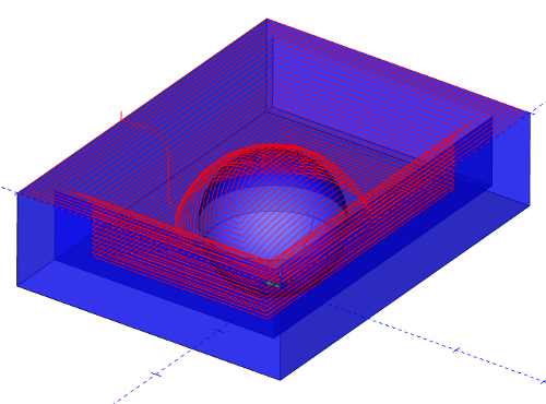
See the following illustration for an example of the toolpath produced.
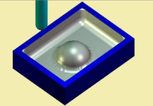
In the simulation window, the end result looks like this.