This operation is used to apply a series of parallel planar cuts to surfaces, solids, or STL data. Using a series of Slice Planar operations in conjunction with the Allowance XYZ option, roughing, semi-finishing, and finishing toolpaths can be generated for the model. When a Slice Planar feature is added to the CAM tree, the system adds the following items.
Geometry - This item is used to assign geometry used to create the toolpath. Right-click this item to produce a shortcut menu with the following options.
Re/Select - Select this option to enable selection mode and assign the appropriate geometry to this feature.
Remove - Select this option to remove any geometry associated with this feature.
Boundary - This allows you to select an area of a part in which to confine the toolpath. Right-click this item to produce a shortcut menu with the following options.
Re/Select - Select this option to enable selection mode and assign the appropriate 2D geometry as a boundary to this feature.
Remove - Select this option to remove any boundary associated with this feature.
Slice Planar - Right-click this item to produce a shortcut menu with the following options.
Edit - This opens the feature wizard so you can modify the settings used to create the toolpath. View the Slice Planar Wizard to learn about the options available for this feature.
Compute Toolpath - When selected, the system calculates the toolpath.
Post Yes/No - This option determines if the feature is included in the posted NC program.
Semi/Finish - Right-click this item to produce a shortcut menu with two options for modifying the computed toolpath.
Color - When selected, a dialog box appears allowing you to change the color of the toolpath.
Blank - When selected, the system hides the toolpath if it is visible or shows the toolpath if it is hidden.
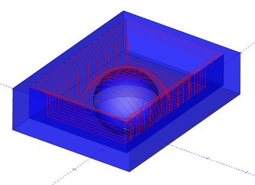
See the following illustration for an example of the toolpath produced.
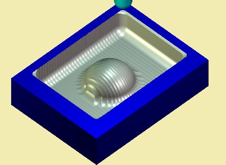
In the simulation window, the end result looks like this.