A semi-finishing or finishing operation generating planar cuts parallel to the machining plane using surfaces, solids, or STL data. These can be processed in a by level or by area processing pattern. Optimal finishes can be obtained on models with vertical or near vertical topology. When a Z-Level Finish feature is added to the CAM tree, the system adds the following items.
Geometry - This item is used to assign geometry used to create the toolpath. Right-click this item to produce a shortcut menu with the following options.
Re/Select - Select this option to enable selection mode and assign the appropriate geometry to this feature.
Remove - Select this option to remove any geometry associated with this feature.
Z-Level Finish - Right-click this item to produce a shortcut menu with the following options.
Edit - This opens the feature wizard so you can modify the settings used to create the toolpath. View the Z-Level Finish Wizard to learn about the options available for this feature.
Compute Toolpath - When selected, the system calculates the toolpath.
Post Yes/No - This option determines if the feature is included in the posted NC program.
Semi/Finish -Right-click this item to produce a shortcut menu with two options for modifying the computed toolpath.
Color - When selected, a dialog box appears allowing you to change the color of the toolpath.
Blank - When selected, the system hides the toolpath if it is visible or shows the toolpath if it is hidden.
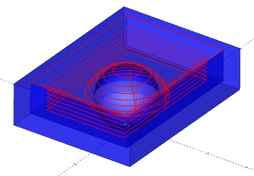
View the following illustration for an example of the toolpath produced.
In the simulation window, the end result looks like this.
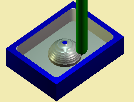
This image was roughed prior to applying the Z-Level Finish toolpath.