This option is used to create a slot or groove on the face of a part or the diameter of a part, dictated by the orientation of the selected geometry. When this feature is added to the CAM tree, the following items are also added.
Geometry - This item is used to assign geometry used to create the toolpath. Right-click this item to produce a shortcut menu with the following options.
Re/Select - Select this option to enable selection mode and assign the appropriate geometry to this feature.
Remove - Select this option to remove any geometry associated with this feature.
Groove - Right-click this item in the CAM tree to produce a shortcut menu with three options.
Edit - When this option is selected, a dialog box appears to provide you with options for modifying the settings that are used when calculating the tool movements. See the Groove dialog box for more detail on the values that are included for this feature.
Compute Toolpath - When this option is selected the system calculates the tool movements for the feature.
Post Yes/No - This option allows you to determine whether the feature is included with the posted program or not.
Semi/Finish - Right-click this item in the CAM tree to display two options for modifying the color and visibility of the feature.
Color - When this option is selected, a dialog box appears allowing you to select a color to use for the displayed toolpath.
Blank - When this option is selected, the system hides the selected toolpath if it is visible in the graphics area, or shows the toolpath if it was previously hidden.
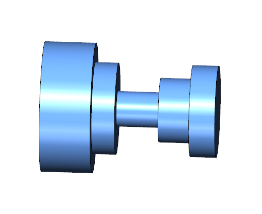
An example Groove toolpath is shown next:
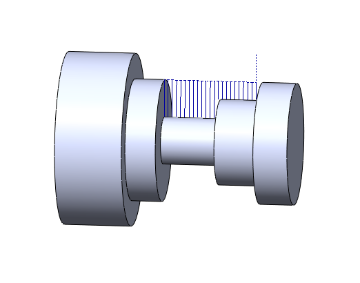
The same part, after simulation, is shown next: