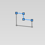
Sketches
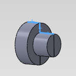
Edges
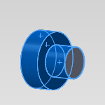
Faces
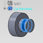
Features
When selecting geometry for Turning features you have multiple options. When using a Turning feature you can select sketches, edges, faces, and features from the SolidWorks FeatureManager design tree.
|
Sketches |
Edges |
Faces |
Features |
|
|
|
|
|
You cannot select a combination of faces and edges. You can only select sketches and edges for a single Turning operation, or select faces and CAD features containing faces for a single turning operation.
The Lathe Selection Manager
Selection Options
Select Whole Bodies - Selecting this check box allows you to select an entire body to be processed by the Turning feature.
The Selected Items list shows all of the currently selected items for the feature. You can right-click in the selection window if you want to delete items, or clear all items, from the selection.
Lathe Parameters
First Section Plane Start Angle - The reference angle to which BobCAM begins analyzing the profile of the feature geometry.
NOTE: Zero degrees is the XZ-plane
Interval angle between section planes - A new section plane is created at this interval for determining the profile of the part.
Preview section planes - Shows the section planes location on the part.
Remove first vertical line - Removes the first vertical line from the detected feature geometry.
Remove last vertical line - Removes the last vertical line from the detected feature geometry.
Primary region only - Allows only primary regions of a part to be included in the detected feature geometry.
More about detected feature geometry and Primary and Secondary Regions