This tutorial explains the process of turning in BobCAM for SolidWorks. Assigning a machine coordinate system, setting up the stock, inserting features, selecting geometry, computing toolpaths, and posting code are all covered. Follow the steps listed to complete the process. Images are included to show the results of each step.
Step 1
Open the AdvancedTurningTutorial1.SLDPRT file located in the C:\BobCAD-CAM Data\BobCAM V2\Examples folder.
Step 2
Click the ![]() BobCAM
CAM Tree tab in the SolidWorks
FeatureManager panel and click
BobCAM
CAM Tree tab in the SolidWorks
FeatureManager panel and click ![]() to expand
to expand
![]() Turning
Stock.
Turning
Stock.
Step 3
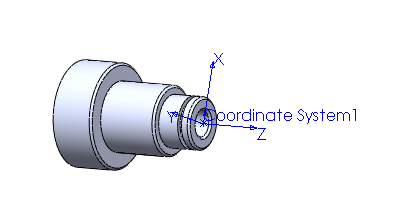
In order to define the zero location on the part, right-click (click
with the right mouse button) ![]() Machine
Setup and click Re/Select.
Machine
Setup and click Re/Select.
Step 4
Click Coordinate System 1, which
has already been created and click  OK.
OK.
Step 1
In the ![]() CAM
Tree tab, right-click
CAM
Tree tab, right-click ![]() Turning
Stock and click Edit.
Turning
Stock and click Edit.
Step 2
Type the following values in the Stock dialog box:
Face Z |
0.0600 |
Cutoff Z |
-4.0000 |
End of Stock Z |
-4.0000 |
Stock Diameter |
3.5000 |
Internal Diameter |
0.0000 |
Click OK to close the dialog box and save the stock settings.

Step 1
Under  Turning
Stock, right-click
Turning
Stock, right-click ![]() Machine
Setup and click Turn, Rough. The Feature
Rough is added to the CAM
tree.
Machine
Setup and click Turn, Rough. The Feature
Rough is added to the CAM
tree.
Step 2
Under Feature Rough, right-click
![]() Geometry
and click Re/Select. Select the
front face of the part. Click
OK.
Geometry
and click Re/Select. Select the
front face of the part. Click
OK.
Step 3
To edit the Rough feature, right-click ![]() Rough
and click Edit.
Rough
and click Edit.
Step 4
In the Rough page, under Cycle Type select Face Rough.
Step 5
In the Leads page type the following values:
Lead In Z |
0.0000 |
Lead Out Z |
0.0000 |
Lead In X |
1.2500 |
Lead Out X |
-0.4375 |
Click OK.
Step 6
To compute the toolpath, right-click ![]() Rough and click Compute
Toolpath.
Rough and click Compute
Toolpath.
Step 1
Right-click ![]() Machine Setup and click Turn, Rough.
Machine Setup and click Turn, Rough.
Step 2
Right-click ![]() Geometry
and click Re/Select.
Geometry
and click Re/Select.
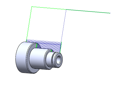
Step 3
Click the Select whole bodies check box and select the part in the graphics area.

Make sure that the Primary region only check box is selected to ignore the groove.
Also, make sure the Remove first vertical line and Remove last vertical line check boxes are selected because the part is already faced.
Click OK.
Step 4
To edit the Rough feature, right-click Rough
and click Edit (make sure it is
the second ![]() Feature
Rough in the CAM tree).
Feature
Rough in the CAM tree).
Step 5
In the Rough page, under Cycle Type select Turning Rough/Finish.
Type the following parameters to leave stock for the finish pass:
Z Allowance |
0.005 |
X Allowance |
0.015 |
Step 6
In the Leads page type the following values:
Lead In Z |
0.1000 |
Lead Out Z |
0.0000 |
Lead In X |
0.0000 |
Lead Out X |
0.1000 |
Click OK.
Step 7
To compute the toolpath, right-click  Rough
and click Compute Toolpath.
Rough
and click Compute Toolpath.
NOTE: The toolpath may automatically compute from switching cycle types in Step 5.
Step 1
Right-click ![]() Machine Setup and click Turn, Groove.
Machine Setup and click Turn, Groove.
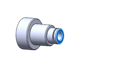
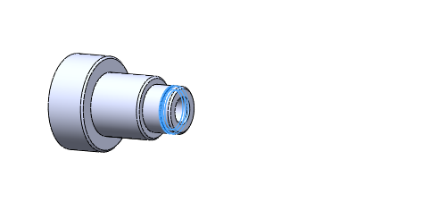
Step 2
Right-click ![]() Geometry
and click Re/Select. In the FeatureManager
design tree tab, click the last Cut-Revolve1
feature. Click OK.
Geometry
and click Re/Select. In the FeatureManager
design tree tab, click the last Cut-Revolve1
feature. Click OK.
Step 3
To edit the Groove feature, right-click ![]() Groove
and click Edit.
Groove
and click Edit.
Step 4
In the Groove page, make sure that under Cycle Type, Turning Rough is selected.
Type the following values:
Z Allowance |
0.000 |
X Allowance |
0.000 |
Step 5
In the Leads page type the following values:
Lead In Z |
0.0000 |
Lead Out Z |
0.0000 |
Lead In X |
0.1000 |
Lead Out X |
0.1000 |
Click OK.
Step 6
To compute the toolpath, right-click ![]() Groove and click Compute
Toolpath.
Groove and click Compute
Toolpath.
Step 1
Right-click ![]() Machine Setup and click Turn, Drill.
Machine Setup and click Turn, Drill.
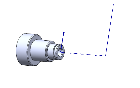
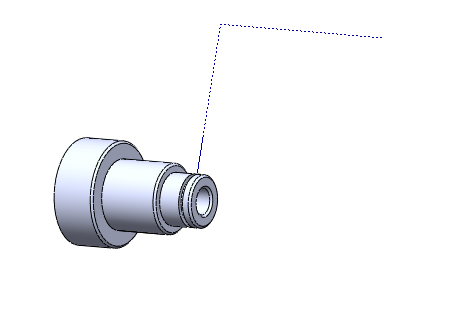
Step 2
Right-click ![]() Start
Point and click Re/Select.
Click the cylindrical face of the hole. Click OK.
Start
Point and click Re/Select.
Click the cylindrical face of the hole. Click OK.
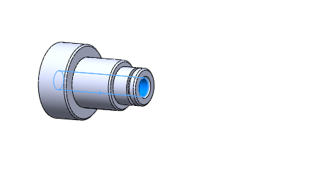
Step 3
To edit the Drill feature, right-click ![]() Drill
and click Edit.
Drill
and click Edit.
NOTE: Notice that the total depth, as well as the drill size, has been set from the geometry selected.
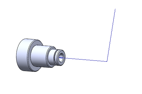
Step 4
To compute the toolpath, right-click Drill and click Compute Toolpath.
Step 1
Click ![]() to expand the (CAM
Part)
to expand the (CAM
Part) ![]() AdvancedTurningTutorial1
folder at the top of the
AdvancedTurningTutorial1
folder at the top of the ![]() BobCAM
CAM Tree.
BobCAM
CAM Tree.
Step 2
Right-click ![]() Turning Tools and click Post. The posted code is displayed
in the
Turning Tools and click Post. The posted code is displayed
in the ![]() Posting
Tab.
Posting
Tab.
NOTE: This uses the ![]() Post Processor selected under
Post Processor selected under
![]() Turning
Stock.
Turning
Stock.
This concludes the Advanced Turning Tutorial.