Tech Tuesday is a weekly blog that addresses some of the most common questions and concerns that I hear throughout the previous week from users of BobCAD-CAM software. Both customers and future customers are more than welcome to leave a comment on what they would like to see covered for the following Tech Tuesday. Enjoy!
![]() Let’s say you have a logo and a curved surface; what are the steps you should take to engrave that logo on the curved surface? Let’s take a look at what we need to do using BobCAD’s CAM software.
Let’s say you have a logo and a curved surface; what are the steps you should take to engrave that logo on the curved surface? Let’s take a look at what we need to do using BobCAD’s CAM software.
In this example, you’ll need 2 sets of geometry. You’ll need geometry to create the curved surface and you’ll need the logo you want to engrave. You can create this geometry in the same drawing file, or you can create 2 files and merge them together later.
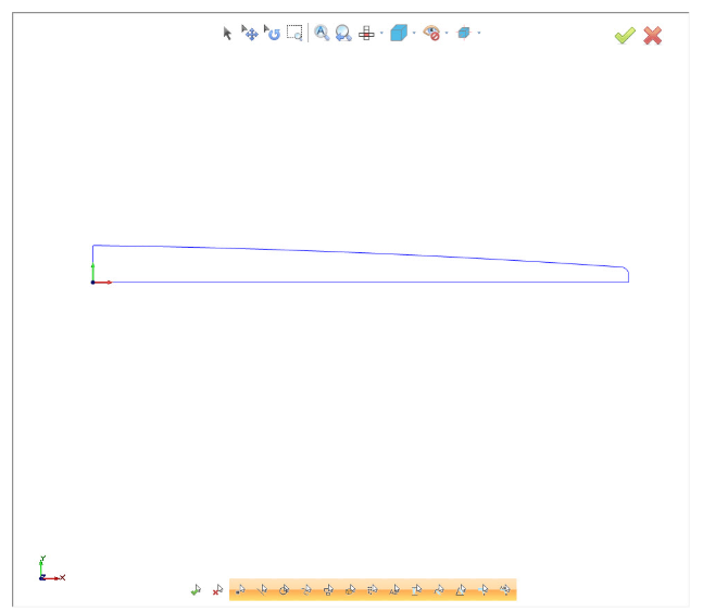
In this example, we are working on a clutch cover plate. We’ve created wireframe geometry to revolve for the curved surface.
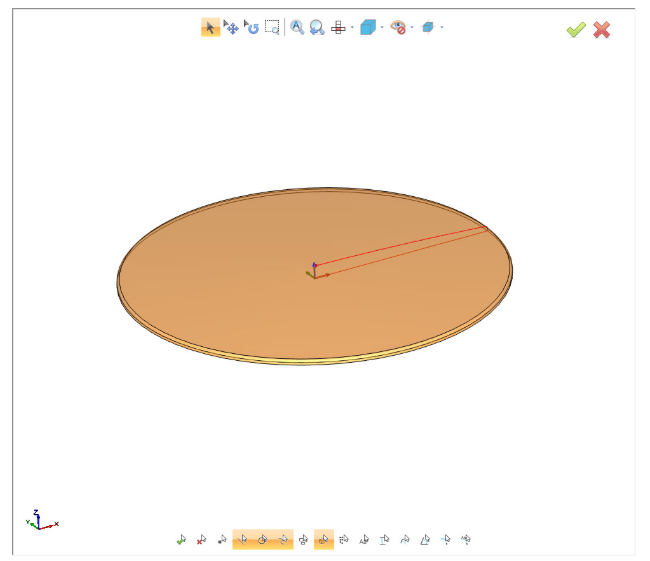
Now that we have our revolved surface, we are ready to work with a Logo. The below DXF file was supplied by the customer.
![]()
So at this point, the clutch cover and logo are in 2 separate CAD files. We want to merge the files together so we can work with them in the same CAD file. The easiest way to do this is to select and copy the logo, then open the clutch cover file, pasting the logo in it. Yes, you can copy and paste geometry from one file into another. A huge time saver and very easy to do.
Pro Tip: Create a new layer and make it active before you paste the logo geometry. This will keep the surface and logo separate, making it easier to select.
Subscribe to BobCAD-CAM's Tech Tuesday Blog
Join your fellow machinists. Get the latest Tech Tuesday CAD-CAM articles sent to your inbox. Enter your email below:Ok, so now we have both geometry sets in the same file… now what? You’ll need to move the logo geometry above the revolved surface. Why? Because we”ll want to project the logo down onto the revolved surface.
Now that we have our logo above our surface, we are ready to project it down onto the surface.
Using project curves, we need our logo and a surface to project down onto. In our example, we revolved the entire profile clutch plate. Now, when we do the projection, we’ll get geometry on the top surface and the bottom. You will want to delete the geometry on the bottom surface. This leaves us with our curved geometry & we are ready to begin engraving in 3D.
Now that we have our geometry setup, we are ready to set up our CAM Tree.
We’ll go to the CAM tab, click on new job and pick Milling & our Milling machine. With this example, we’ll use the revolved surface as our stock model. The stock type we will be using is the solid model type.
 Our next step is to load a machining feature. In this demonstration, we are going to use 3 axis wireframe.
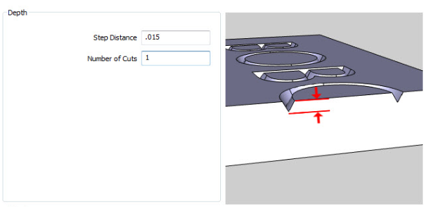
We’ll select our geometry, pick a tool and set the depth.
Our next and final step is to compute the toolpath. After you do that, that’s it! We are ready to simulate to make sure everything looks right, and post our code. Pretty simple, huh? Thank you for reading another Tech Tuesday; see you next week!

Start your Test Drive.
Have questions? Call us at 877-838-1275.
You’re one click away from subscribing to BobCAD’s YouTube channel. Click the link below for tips, how-tos and much more!


Leave a Reply