In the BobCAD-CAM system when using the multi-axis features your machine must be properly defined. The calculations that must be performed for proper G-Code creation depends on an accurate definition of your machine’s kinematics. This document covers how to find the center of rotation for a 5-axis Table-Table machine with a tilt rotary unit so the machine parameters can be correctly defined.
There is a simple test you can use to find the necessary values and we will walk you through this process here in this document.
Overview of the required steps:
- Locate 2 point locations on the rotary platter in 2 orientations of the tilt/rotary unit 90 degrees apart.
- Using the CAD system, draw the 4 points and create the geometry that will show the center of rotation.
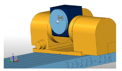
Step 1 –Locate the X Axis and Z Axis Positions of the 1st Point (P1)
The 1st point we need to locate is at the center of the face of the rotary platter. The following image shows the location of the point we are looking for.
Important Note: This document shows a tilt/rotary unit that when at Zero-Zero (both rotation angles at zero), location has the tilting axis sitting where the rotary is aligned to rotate around the X axis. If your zeroing your assembly at a different location, simply apply what you see here to your orientation.
To find this location on your machine, use a tool to touch the face of the platter to find your X axis component. Use the bottom of the tool to touch off the edge of the rotary platter then account for the radius of the platter to get the point at the center. We will call this P1
Note the X axis and Z axis positions of this point. (X, Z).
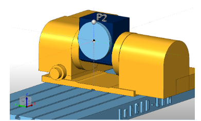
Step 2 – Locate the X Axis and Z Axis Positions of the 2nd Point(P2)
To find the 2nd point leave the tilting axis in the same position and locate the edge of the rotary platter making sure to stay in the same Y axis planeand X axis planeas shown in the following image. The Z coordinate should be the only difference.
Note the X axis and Z axis positions of this point. (X, Z).
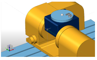
Step 3 – Locate the X Axis and Z Axis Positions of the 3rd Point(P3)
To find the 3rd point you need to rotate the tilting axis to a position that will hold the rotary platter,so it is facingthe Z axis of the machine tool. The following image shows the location we are looking for.
Step 4 – Locate the X Axis and Z Axis Positions of the 4th Point(P4)
Find the edge of the platter in the X+ direction so you are finding the same platter location as in Step 2 but now in this rotated position as shown in the image below.
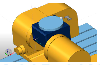
Note the X axis and Z axis positions of this point. (X, Z).
Step 5 – Use the CAD system to find the center of rotation
Create 2 lines using the following point locations in the CAD system.
Line 1 –Use point P1 and point P3
Line 2 –Use point P2 and Point P4
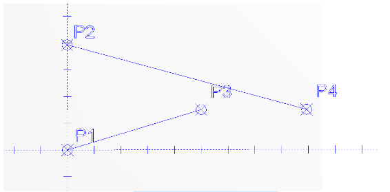
These points represent the same two locations on your tilt rotary unit when the unit is in the two different positions. The following image shows an example of these points from a FRONT view. Your point locations will vary.
Next we need to create lines that are perpendicular from these two entities at their midpoint. The lines should extend in the direction of the center of rotation.
Use the Trim Two option to trim the two perpendicular lines to each other. The intersection point of these two lines is the center of rotation. The following image shows the result of these steps.
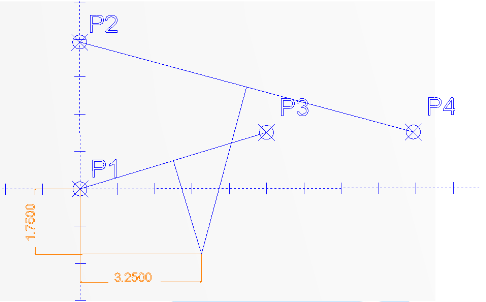
You can now measure the X dimension and Z dimension from a known point. In this example we have taken measurements from point P1 to the center of rotation.
Center X:________
Center Y:________
BobCAD-CAM has provided CAD-CAM CNC Software products to the global manufacturing industry for over 30 years. BobCAD-CAM software can be found to increase CNC productivity for many applications in aerospace, automotive, production manufacturing, mold making, general machining, woodworking as well as the medical manufacturing industry, consumer products, musical instruments, custom fabrication, defense industry and many others due to the products ability to automatically generate NC programming code for such a wide variety of CNC controllers. BobCAD-CAM software is also found in educational institutions throughout the world as well as independent hobby home use. Products include machining technology for 2, 3, 4 & 5 Axis CNC Milling, Routing, Waterjet, Plasma and Laser machines as well as 2 Axis CNC Lathe. BobCAD-CAM is modular allowing shops to start off at a reduced technology level and add technology as it is needed including an add-on, BobART, for artistic machining. Unique technology includes adaptive high-speed machining multiaxis milling and routing which is a first in the world of CAD-CAM software. BobCAD-CAM also provides a variety of quality training products that include regional and online training classes or private sessions tailored to specific applications. Professional certification and multi-tiered support solutions are available. Contact BobCAD-CAM directly for more information at 877-262-2231 or 727-442-3554


Leave a Reply