Tech Tuesday is a weekly blog that addresses some of the most common questions and concerns that I hear throughout the previous week from users of BobCAD’s CNC software. Both customers and future customers are more than welcome to leave a comment on what they would like to see covered for the following Tech Tuesday.
The purpose of the facing operation is to clean up the top of the stock material. Exactly how this operation is performed is dictated by the settings of the operation. Using the settings can define a facing operation to resurface a spoil board for your router.
When facing a spoil board in BobCAD, the user will first need to set up the stock, machine setup, and toolpath before sending the code to the machine. This document will provide a brief tutorial on how you might go about creating and posting a CAM Job using a facing operation for the spoil board.
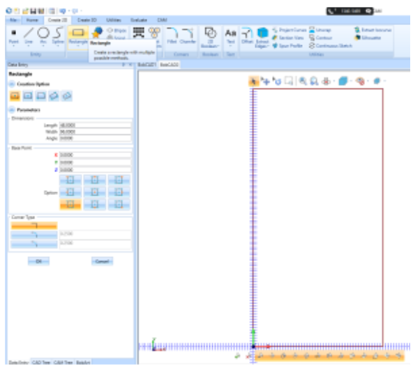
In the Create 2D tab, select the Rectangle option. For the length and width of the rectangle, input the values of the spoil board that is being faced. This example will use a 4’ x 8’ spoil board or 48” x 96” (Length x Width). In the Base Point section, select the bottom left corner option to place the geometry in the upper right-hand quadrant. Click OK, then Cancel.
Right-click on CAM Defaults in the CAM Tree and select New Job. For the “Job Type”, select Milling and choose your machine from the drop-down if it’s not already there by default. Then, click Stock Wizard. We can skip the Workpiece page since we do not have a solid model of the workpiece. We can leave the stock rectangular and a bounding box around the stock we previously drew.
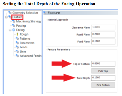
Right-click on the Machine Setup – 1 in the CAM Tree and select Mill Facing. On the Geometry Selection page, no action is needed. The software will use the info from the Stock Wizard that we setup in the previous steps. Click Next. On the Feature page (shown in the image below), keep the Top of Feature set to the default as this value is automatically set to 0.0000. This is because our top of the stock is in relation to the Machine Origin. Adjust the Depth to the depth of the cut from the top of the spoil board. In this example, we will leave this value set to 0.1000. Click Next until you get to the Tool Page (Rough).
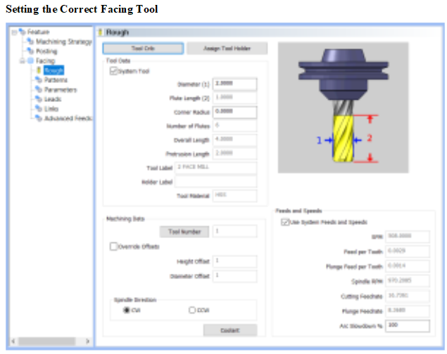
On the Tool Page (Rough) (shown in the image below), choose the tool that will be used in the facing feature. In this example, a 2 Diam Face Endmill will be used.
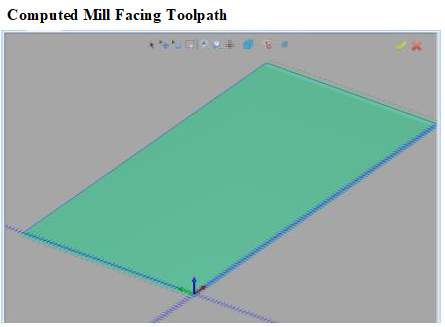
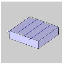
On the Patterns page, set the Stepover (Distance between each pass) for the feature. The default is set to 50%. For this example, set the Stepover to 75%. This would set the Stepover distance to 1.5 inches. We will leave the other pages to the default settings and click Compute at the bottom right.
On Workpiece – keeps the toolpath contained within the bounds of the part and enables the Distance (% of Tool Diameter) box.
Distance (% of Tool Diameter) – 50 percent of the tool diameter will cancel out the offset and contain the toolpath to exactly 4’ x 8’ across the spoil board. Compute the feature again to update the toolpath.
If you are happy with the results and want to send the G-Code to your machine, Right-click in the Posting window and click Save As to save to a flash-drive. If you are in the NC Editor, go to File > Save > Save As to save to a flash-drive or go to the Tools tab and click Start DNC Transfer to send the g-code through a RS232 cable.
This information is also found in our Knowledgebase for common questions about various functions in BobCAD-CAM. Our Knowledgebase documentation can be found here: https://bobcadsupport.com
Download a free demo version of BobCAD-CAM today!
Our support site allows you to submit a ticket to technical support online:
www.bobcadsupport.com Our user forum is a community of other BobCAD-CAM users to share ideas and projects in BobCAD-CAM:
forum.bobcad.com
BobCAD-CAM has provided CAD-CAM CNC Software products to the global manufacturing industry for over 30 years. BobCAD-CAM software can be found to increase CNC productivity for many applications in aerospace, automotive, production manufacturing, mold making, general machining, woodworking as well as the medical manufacturing industry, consumer products, musical instruments, custom fabrication, defense industry and many others due to the products ability to automatically generate NC programming code for such a wide variety of CNC controllers. BobCAD-CAM software is also found in educational institutions throughout the world as well as independent hobby home use. Products include machining technology for 2, 3, 4 & 5 Axis CNC Milling, Routing, Waterjet, Plasma and Laser machines as well as 2 Axis CNC Lathe. BobCAD-CAM is modular allowing shops to start off at a reduced technology level and add technology as it is needed including an add-on, BobART, for artistic machining. Unique technology includes adaptive high-speed machining multiaxis milling and routing which is a first in the world of CAD-CAM software. BobCAD-CAM also provides a variety of quality training products that include regional and online training classes or private sessions tailored to specific applications. Professional certification and multi-tiered support solutions are available. Contact BobCAD-CAM directly for more information at 877-262-2231 or 727-442-3554
New Feature Spotlight – Tell us the topics that are most important to you Click Here


Leave a Reply