Subscribe to BobCAD-CAM's CNC Software Blog
Join your fellow manufacturers! Get BobCAD-CAM’s latest CAD-CAM articles straight to your inbox. Enter your email below:1) How do I rotate a part?
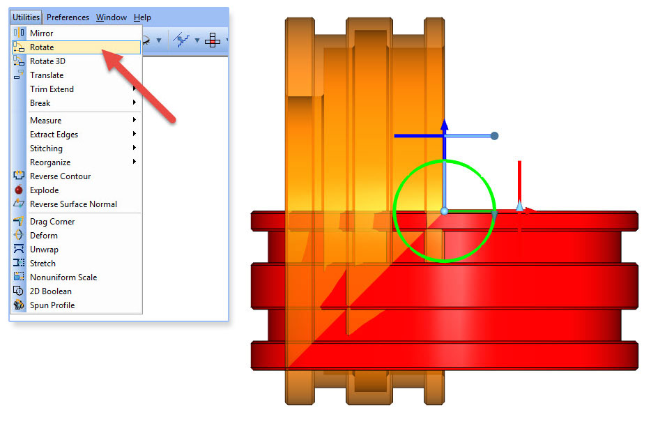
You’ll find the rotate option under the utilities menu. Once you initialize the rotate feature, you’ll select your part and either enter the rotate amount in the dialog box or use the dynamic drawing handles to rotate your part the appropriate direction and degrees.
2) How do you get wireframe for BobCAM for SOLIDWORKS™?
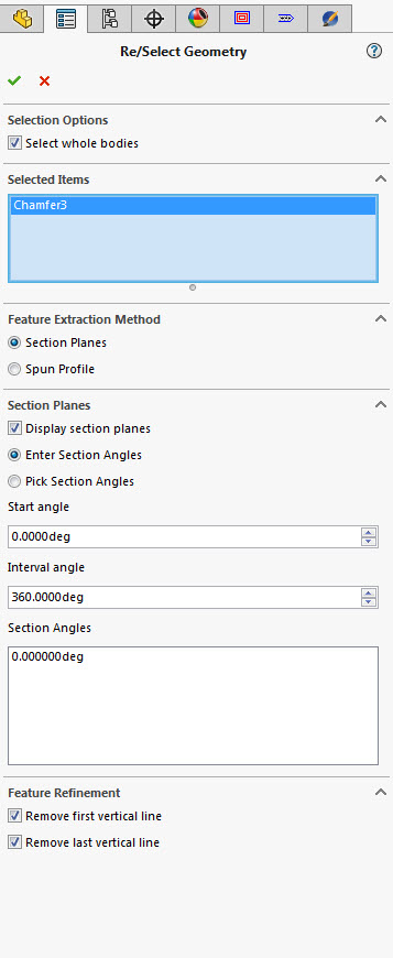
BobCAM doesn’t require wireframe or “sketches” to program turning cycles. You can apply toolpath directly to the body or surfaces using either the section plane or spun profile option. You can also apply toolpath to sketches.
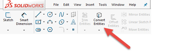
In SOLIDWORKS, there are many ways to create sketches. You could convert entities based on the sketches used to create the body you are working with.
3) Can you use MDI input to manually tell the tool where to go?
Not in our 2 axis Lathe software, unless you use a scripted post and advanced posting API. Use this link from our help system to learn more.
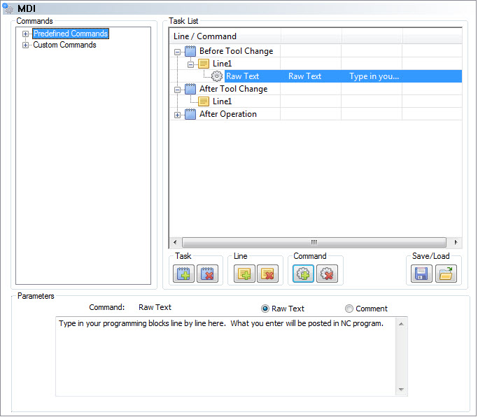
If you’re using our Mill Turn software, we do offer an MDI programming block that you could use to input blocks of code that you want to post in your program. This includes entering custom blocks of code to tell your tool where you want it to go, line by line. You can also save programming blocks for future use – just like creating a macro and calling it up for use later.
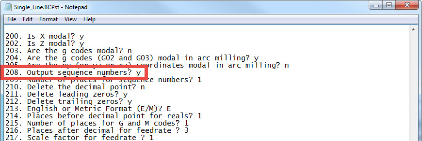
4) Can you change the posted code to show line numbers?
Yes, you can edit your post processor to turn line numbers on or off as needed. You would edit your post in notepad, go to block 208 and change the output sequence numbers. Setting the value to N will turn off line numbers – setting the value to Y will turn line numbers on. Once you change the setting, save the file and then re-post your program.
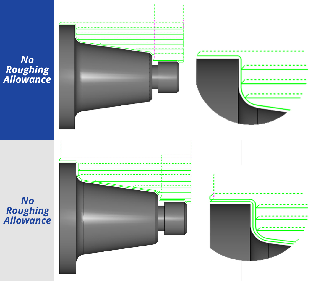
5) How do you control how much material you leave for roughing cycles?
The parameters page of the Lathe wizard is used to define your depth of cut, rough allowance and finish allowance. This is where you can independently define the stock you want to leave for finishing in X and Z.
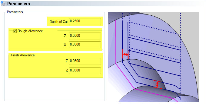
New to BobCAD-CAM V29 is the rough allowance, which provides a semi-finish pass on your part profile as part of your roughing cycle.
6) Why do I get so many lines of code when using collision detection?
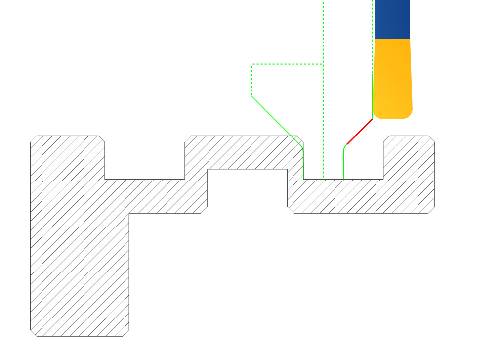
Additional toolpath motion will be created to avoid a collision with your insert and holder for your part profile. Depending on the collision that is occurring, a few movements or many movements may need to be created in order to “bump up” your tool insert and holder out of harm’s way.
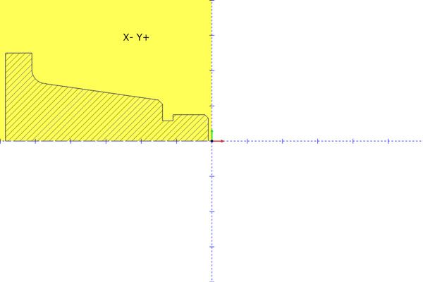
7) How do you “tell” the software the location of the tool turret – whether it’s in front of or behind the spindle?
You don’t – the part location in BobCAD-CAM’s drawing environment must be in the Y+ and X- quadrant. The posted code for turning cycles will be XZ. If you are using a front post lathe, or a turret style, the code would also be XZ. So you don’t have to “tell” the software where the turret location is.
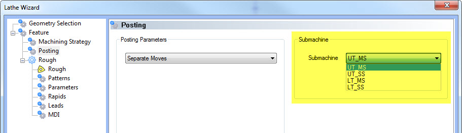
When using a mill turn machine, you may have both an upper and lower turret. You also may have a main spindle and sub-spindle. We use a sub-machine to pair the spindle and turret you are programming with. You would use the same part location and geometry selection as 2 axis turning. Users just select the sub-machine to pick the turret and spindle pair they are programming with.
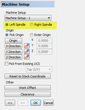
I think it’s also important to note that the Mill Turn module supports multiple setups. When creating a machine setup, you choose which spindle the part is being held in – either the left or the right spindle.
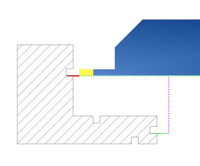
8) When grooving, how do you program the chamfer edges?
The groove roughing cycle is used to remove the bulk of the material. When it comes to finishing, you’ll use the groove finish cycle. This is when you’ll “profile” the part geometry, which includes a chamfer or radius on the edge of the part.
9) Can you add a dwell value to the grooving cycle?
Not with the in-box features. To add a dwell, you would need to use a scripted post and the advanced posting tab, allowing you to create a checkbox to turn the dwell on and an input box for how long the dwell would be.
10) How do you change the posted code from radius to diameter?
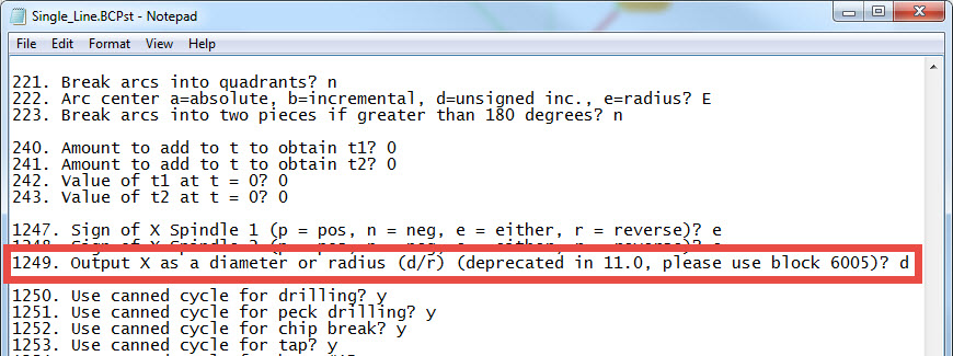
Posting in radius or diameter is based on your post processor settings. You can edit your post in notepad to make this change. Changing the 1249 block from R to D will change your posted code from radius to diameter.
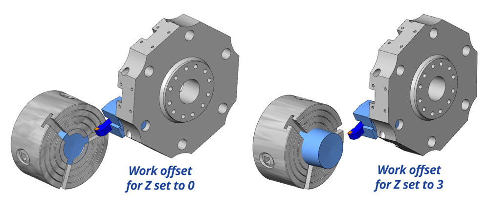
11) How do you check how far the part is sticking out from the check before running simulation?
Machine simulation is not offered for 2 axis turning. So the only chuck display would be one you’ve drawn into your file. The Mill Turn module uses the machine setup work offset locations to move the part off the face off the chuck.

Adjusting the Z value is used to define how far the stock geometry is away from the chuck face.
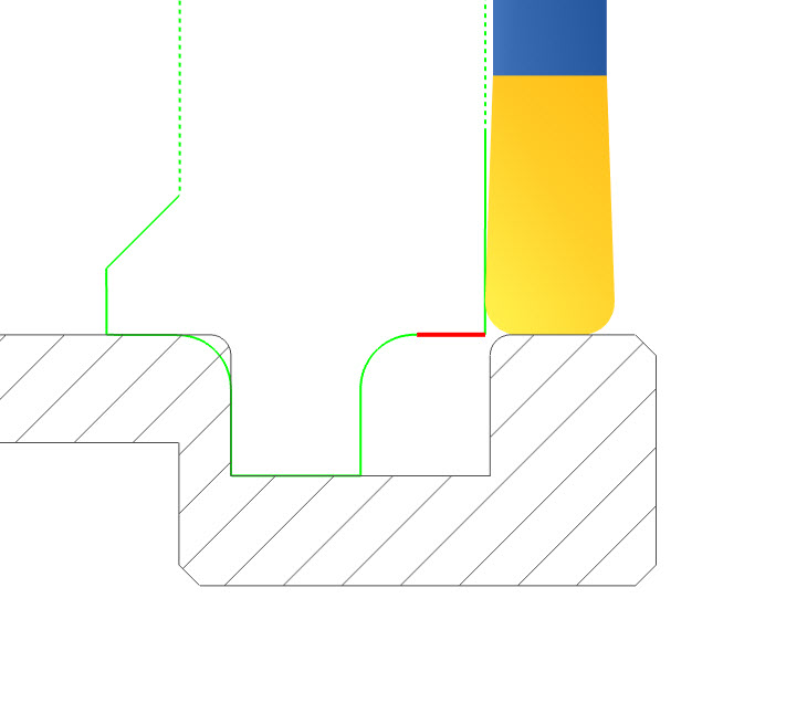
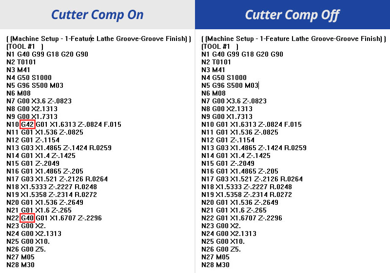
12) If you have groove with a radius on the edge – how do I properly use cutter comp?
If you turn cutter comp on and your post is configured properly for your machine, you should have no issues.
13) Can you face groove?
Yes – using the feature programming, you can choose OD, ID, front face or back face groove locations.
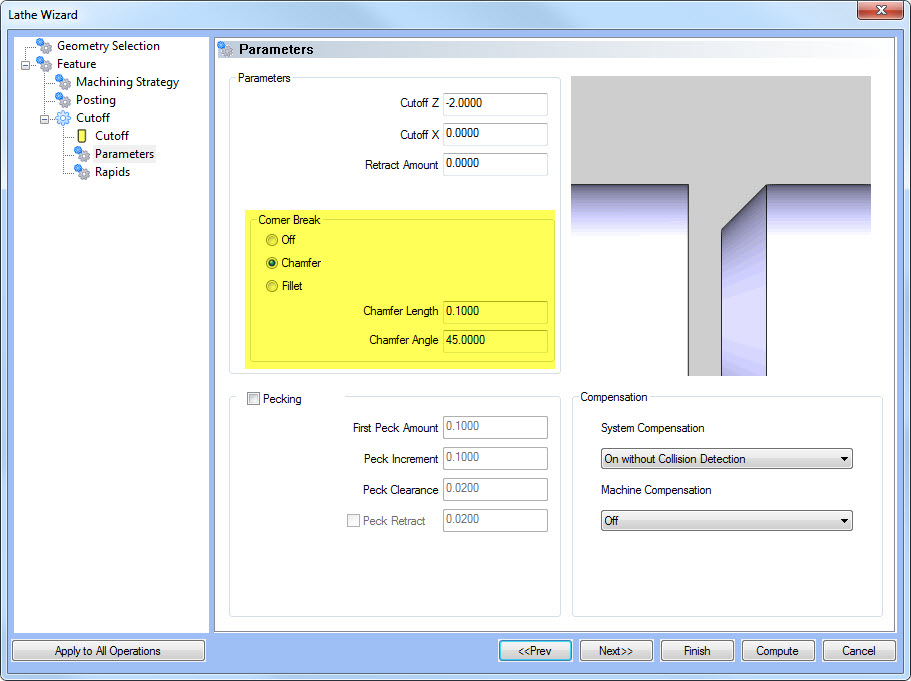
14) Can you chamfer the edge of a part using the cut off cycle?
Yes, we offer 2 edge breaking options when performing your cut off.
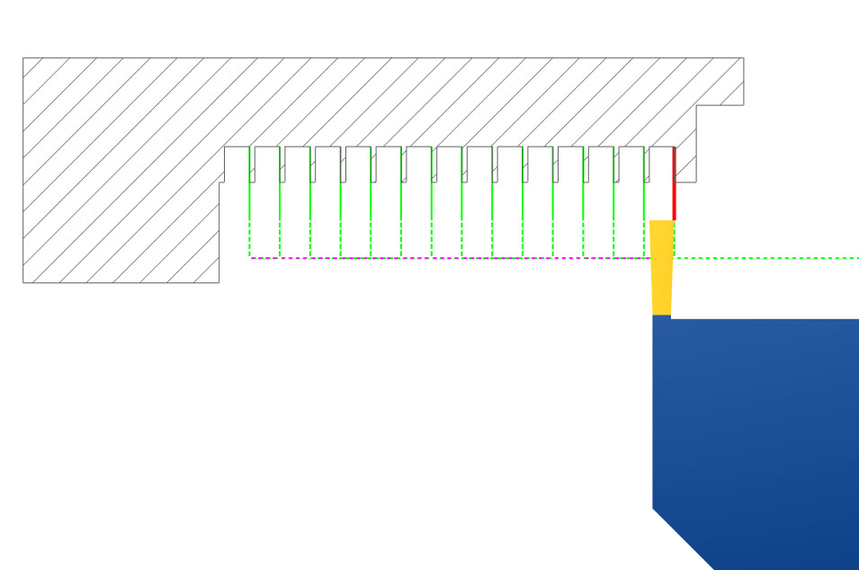
15) What is the best way to make copies of a groove – like 50 in a line?
The best way is to draw the first groove and translate with copies for each additional groove. Once the geometry is created, you can apply the groove toolpath to multiple groove geometry sets at one time.
16) How do you set or change the default tool for a rough/finish or groove cycle?
There are 2 ways to accomplish this:
a) Load a tool crib – this way each default tool type would be based on the tools loaded in your tool crib.
b) Use save and load or copy and paste to save machining features with your tool information.
I prefer the 2nd method because it not only saves your tool information. It also saves all the cutting settings, speed and feeds – making it fast to program common operations.
17) What is the best way to learn about the CAD side of BobCAD-CAM?
The best way to learn the CAD software is to purchase one-on-one web training. This way you can send us a print and we can walk you through step by step how to draw your part. You’ll also get a video recording of the training session to refer back to or to use with other employees.


Leave a Reply