Tech Tuesday is a weekly blog that addresses some of the most common questions and concerns that I hear throughout the previous week from users of BobCAD-CAM software. Both customers and future customers are more than welcome to leave a comment on what they would like to see covered for the following Tech Tuesday. Enjoy!
Damaging a tool can be an expensive mistake, but damaging a machine is much more costly to you and your shop. BobCAD-CAM helps you avoid losing profitability with one simple feature; Machine Simulation. Machine Simulation comes standard with BobCAD’s Mill Turn software, allowing you to check your tool, holder, adapter, jaws and workpiece for collisions. How does it work? Very simply, let’s check it out.
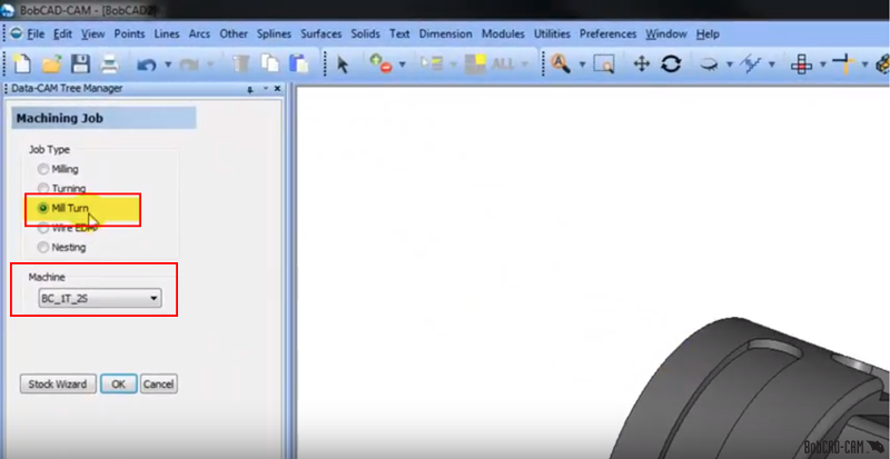
When creating a new machining job for a Mill Turn part, you will have to select a Mill Turn job type under ‘Machining Job’ in your DATA CAM Tree Manager and also the machine you will be using. Hit OK to move forward in your job.
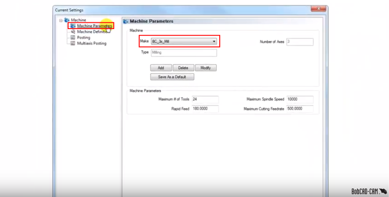
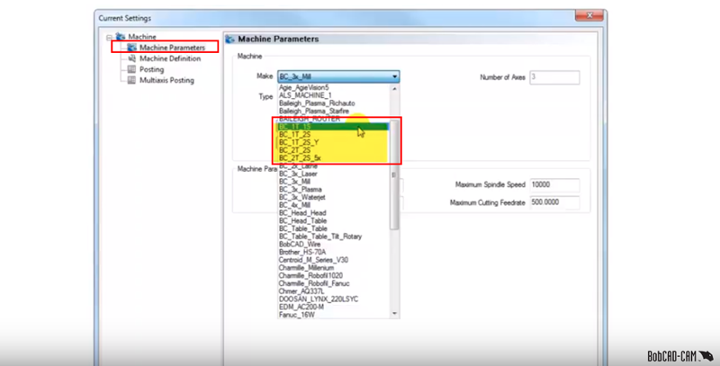
Our next move is to examine and alter our machine settings. In the DATA CAM Tree Manager, go to ‘CAM Defaults’, right-click and then select ‘Current settings’. With our ‘Current Settings’ tab open, go to ‘Machine Parameters’ and we’ll choose one of the Mill Turn machines under ‘Make’.
You will notice that there are a number of standard Mill Turn machines already built in the software. They present themselves as the ‘BC_1T_1S’ through ‘BC_2T_2S_5X’.
Collision Checking:
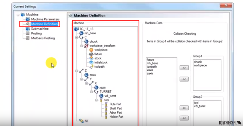
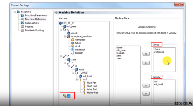
Collision checking in BobCAD CNC software can be found and examined in the Current Settings tab under ‘Machine Definition’. Clicking Machine Definition shows you all the machine’s components, settings and the configuration of the machine is outlined in the tree structure.
Subscribe to BobCAD-CAM's Tech Tuesday Blog
Join your fellow machinists. Get the latest Tech Tuesday CAD-CAM articles sent to your inbox. Enter your email below:At the bottom left of the tree, you will notice the initials ‘cc’. This is your collision checking feature. On the right where your machine data is displayed, you will see in the first column that all the machine components are laid out. In the right, we can check the components in Group 1 vs the components in Group 2. Using our collision checking groups, we can check the tool, holder, chuck, the workpiece or any of the machine components against each other for issues during live machining.
Machine Simulation:
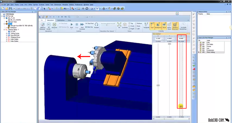
Jumping back into Machine Simulation, let’s take a look at these collision checking groups in action. To the left of my layers tab is my Axis Control window. I’m going to take control of my Z Axis and bring at along towards my chuck.
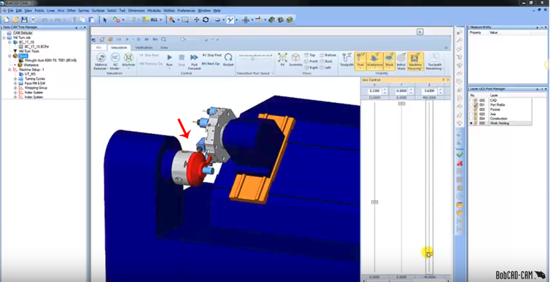
You will notice that as my tool holder makes contact with my chuck jaws, the colored red is an indicator that there will be a collision between one machine component and another. This is the purpose of collision checking groups; if there is a collision between on machine component or another, it will show up as either a proximity report or a red color (indicating collision). Thanks again for reading another Tech Tuesday; see you next week!

You’re one click away from subscribing to BobCAD’s YouTube channel. Click the link below for tips, how-tos and much more!


Leave a Reply