Tech Tuesday is a weekly blog that addresses some of the most common questions and concerns that I hear throughout the previous week from users of BobCAD’s CNC software. Both customers and future customers are more than welcome to leave a comment on what they would like to see covered for the following Tech Tuesday.
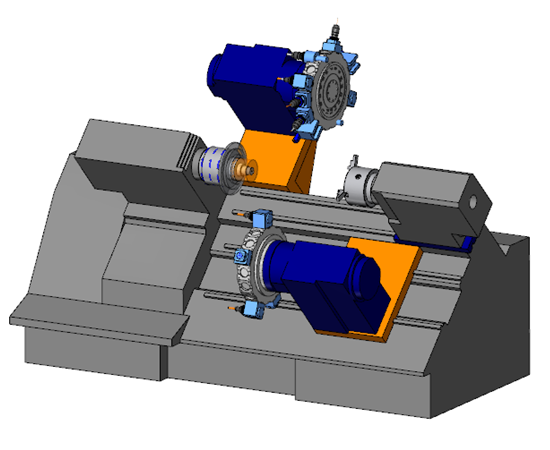
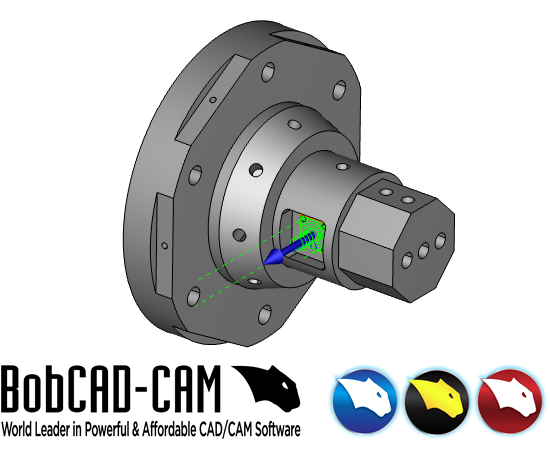
In this Tech Tuesday, we will be reviewing a part file that was programmed using our Mill Turn functionality. Mill Turn can also be described as a lathe with live tooling. It most commonly is a lathe that has a turret that can include turning tools as well as milling tools. BobCAD-CAM supports mill turn machines with multiple turrets and multiple spindles. If your Mill Turn CNC machine has a sub spindle for example, BobCAD-CAM is able to support the part transfer from one spindle to the other. In the sample part file shown, we will be looking at a few different operations in our Mill Turn package. The first operations are going to be turning down the stock initially. The next operations are going to be drilling the holes on the front face of the stock and then milling around the top profile. Lastly, we will be taking a look at creating a new index to mill a pocket on the side face of the stock.
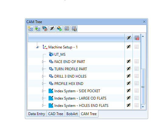
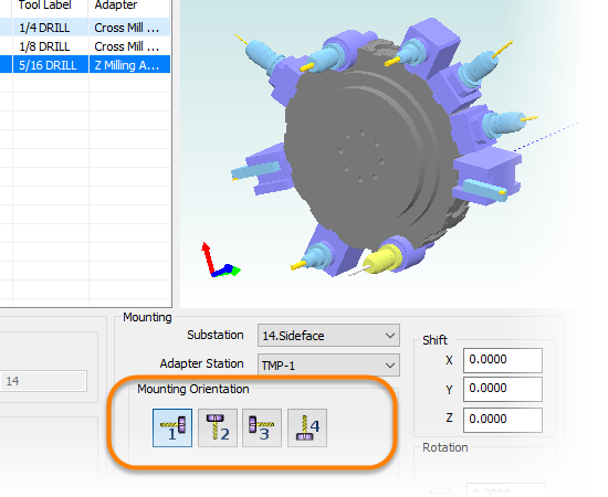
First, we will be going through the turning operations to turn down the cylindrical shape of our sample workpiece. You can see the toolpath that includes a facing operation, and then a roughing operation and a finish pass along the profile of the part. The operation selection and the workflow of the turning operations are the very same as in our Lathe package of BobCAD-CAM. You would be selecting the geometry for the operation, the different operation types, and then selecting the tool you are using. In the Mill Turn package, you would then be defining the station number the tool will be designated to in the turret and the specific orientation of the tool. By defining each tool in each station of the turret, you will be able to view each tool in simulation to avoid any collisions. After defining the turning tools, the workflow will again be the same as the Lathe package of BobCAD-CAM. You would then set other parameters such as feedrates, depth of cut, lead-in/lead-out, etc.
In the Mill Turn package, you would then be defining the station number the tool will be designated to in the turret and the specific orientation of the tool. By defining each tool in each station of the turret, you will be able to view each tool in simulation to avoid any collisions. After defining the turning tools, the workflow will again be the same as the Lathe package of BobCAD-CAM. You would then set other parameters such as feedrates, depth of cut, lead-in/lead-out, etc.
The next operations will include the drilling and milling operations on the front face of the stock. Just as in the turning features, the milling features in the Mill Turn package will have the same workflow as the Mill modules of BobCAD-CAM. Select the milling operations you will be utilizing, select the geometry, and then set all of the similar parameters as you would in the milling operations. In the image below, you can see the drill operation and the milling operation to profile around the front face. On the tool page for each operation, the tools will be defined and placed on a station of the turret. The tools will also be oriented to be pointed towards the front face of the stock.
Our last operation to inspect on this part will be the pocket operation on the side of the stock. This pocket can only be machined if the mill turn machine you are operating has the capability of the milling tools to travel in the Y axis. To begin with programming this pocket operation, we right-click on the Machine Setup and go to Additional Functions. We then select the option Add Index.
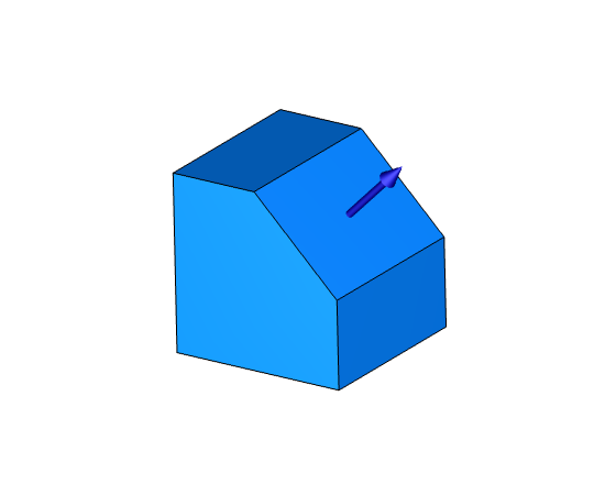
In the geometry selection of the index, you can pick a surface for the new direction the tool will be oriented. The tool will be pointed towards the direction of the surface normal direction you selected. In the geometry selection, you could also select a UCS with the correct Z direction for your tool orientation. After adding the index, you will then create the milling operation under the index. On the tool selection pages of the milling operations, you will need to orientate the tool correctly. The tool will be 90 degrees in relation to the other milling tools on the turret, and the tool will be facing the side of the stock in the simulation.
Download a free demo version of BobCAD-CAM today!
Our support site allows you to submit a ticket to technical support online:
www.bobcadsupport.com Our user forum is a community of other BobCAD-CAM users to share ideas and projects in BobCAD-CAM:
forum.bobcad.com
BobCAD-CAM has provided CAD-CAM CNC Software products to the global manufacturing industry for over 30 years. BobCAD-CAM software can be found to increase CNC productivity for many applications in aerospace, automotive, production manufacturing, mold making, general machining, woodworking as well as the medical manufacturing industry, consumer products, musical instruments, custom fabrication, defense industry and many others due to the products ability to automatically generate NC programming code for such a wide variety of CNC controllers. BobCAD-CAM software is also found in educational institutions throughout the world as well as independent hobby home use. Products include machining technology for 2, 3, 4 & 5 Axis CNC Milling, Routing, Waterjet, Plasma and Laser machines as well as 2 Axis CNC Lathe. BobCAD-CAM is modular allowing shops to start off at a reduced technology level and add technology as it is needed including an add-on, BobART, for artistic machining. Unique technology includes adaptive high-speed machining multiaxis milling and routing which is a first in the world of CAD-CAM software. BobCAD-CAM also provides a variety of quality training products that include regional and online training classes or private sessions tailored to specific applications. Professional certification and multi-tiered support solutions are available. Contact BobCAD-CAM directly for more information at 877-262-2231 or 727-442-3554
New Feature Spotlight – Tell us the topics that are most important to you Click Here


Leave a Reply