Tech Tuesday is a weekly blog that addresses some of the most common questions and concerns that I hear throughout the previous week from users of BobCAD’s CNC software. Both customers and future customers are more than welcome to leave a comment on what they would like to see covered for the following Tech Tuesday.
The Chuck Wizard is used to define a chuck for multi-axis mill turn machines. BobCAD users have the ability to define the specific chuck they are using on their machines to simulate in the BobCAD software program. The Chuck Wizard dialog box is accessed from the Machine Definition of the Current Settings. Here is the workflow to access the Chuck Configuration dialog from the Machine Definition:
- Right-click on CAM Defaults from the CAM Tree
- Select Current Settings
- Select the Mill Turn machine you are using
- Click on Machine Definition
- Click on C axis rotation, where you now can see the button to click on the Chuck Wizard
There are many parameters that you can manipulate in the Chuck Wizard to simulate the chuck you are using, including:
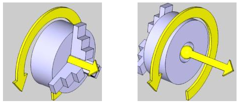
Rotation Axis
The rotation axis of the chuck is set in reference to the machine zero coordinate system. (This defines the rotation axis of the chuck)
Base Point
This parameter determines the distance from the machine zero location or the front face of the chuck, to the chuck rotation axis. (The face of the chuck is aligned to machine zero location when creating the geometry files).
Index Direction
This parameter defines the direction for positive rotation of the chuck, either the clockwise or counterclockwise direction.
Chuck Body
You can either simply type in the certain parameters of the chuck body:
- Body Diameter – sets the overall diameter of the chuck.
- Inner Diameter – sets the inner diameter of the chuck.
- Body Thickness – sets the thickness of the chuck.
Or you can select an STL file for the model of the chuck. You will need to select whether the STL file was modeled in inches or in mm.
Flip Orientation
The direction of the extruded chuck is determined by the rotation axis. The default direction of the extrusion is along the positive of the rotation axis vector. This can be changed by selecting the following check box.
With the checkbox cleared, the chuck body is extruded along the positive direction of the rotation axis.With the checkbox selected, the orientation reverses and is extruded along the negative direction of the rotation axis vector.
Next, you will be defining the parameters of the jaws of the chuck.
There are parameters to set the number of jaws. This determines how many jaws are on the chuck. The jaws are all equally spaced around the chuck. Other parameters for the jaws of the chuck include:
Limits
- Min – defines the minimum amount of travel toward the center of the chuck.
- Max – defines the maximum amount of travel toward the outside of the chuck.
- Initial – defines the initial position of the jaws.
First Jaw Angle
Defines the initial vector direction of the first jaw. Subsequent jaw vector directions are calculated from this position.
Geometry
The dimensions of the chuck body can be defined with manually entered values for each of the parameters:
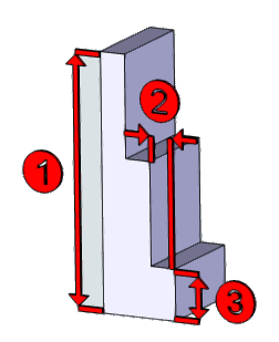
- Jaw Height (1) – sets the height of the jaw.
- Step Height (2) – sets the height of steps in the jaw.
- Step Depth (3) – sets the depth of steps in the jaw.
- Thickness – sets the thickness of the jaw
Or you can select an STL file for the model of each of the jaws of the chuck. You will need to select whether the STL file was modeled in inches or in mm. This way, you can model the chuck and the jaws in the BobCAD simulation to the exact specifications as you have on your machine.
Try the Chuck Wizard for your simulation in BobCAD today!
BobCAD-CAM has provided CAD-CAM CNC Software products to the global manufacturing industry for over 30 years. BobCAD-CAM software can be found to increase CNC productivity for many applications in aerospace, automotive, production manufacturing, mold making, general machining, woodworking as well as the medical manufacturing industry, consumer products, musical instruments, custom fabrication, defense industry and many others due to the products ability to automatically generate NC programming code for such a wide variety of CNC controllers. BobCAD-CAM software is also found in educational institutions throughout the world as well as independent hobby home use. Products include machining technology for 2, 3, 4 & 5 Axis CNC Milling, Routing, Waterjet, Plasma and Laser machines as well as 2 Axis CNC Lathe. BobCAD-CAM is modular allowing shops to start off at a reduced technology level and add technology as it is needed including an add-on, BobART, for artistic machining. Unique technology includes adaptive high-speed machining multiaxis milling and routing which is a first in the world of CAD-CAM software. BobCAD-CAM also provides a variety of quality training products that include regional and online training classes or private sessions tailored to specific applications. Professional certification and multi-tiered support solutions are available. Contact BobCAD-CAM directly for more information at 877-262-2231 or 727-442-3554
New Feature Spotlight – Tell us the topics that are most important to you Click Here


Leave a Reply