Tech Tuesday is a weekly blog that addresses some of the most common questions and concerns that I hear throughout the previous week from users of BobCAD’s CNC software. Both customers and future customers are more than welcome to leave a comment on what they would like to see covered for the following Tech Tuesday.
Today’s Tech Tuesday covers a BobCAD After Dark Facebook Live covering two Thread Milling examples and key features in the BobCAD software for Tapping and Thread Milling.
If you would like to watch the video, use this link below to join the BobCAD After Dark Facebook Group:
https://www.facebook.com/groups/bobcadafterdark/
We host weekly live videos on Tuesdays and Thursdays from Noon to 1PM ET. We look forward to you joining us as we explore the many features found in BobCAD-CAM’s CAD-CAM software.
Now for the topic at hand…Thread Milling.
So what does it take to setup and program thread milling in BobCAD.
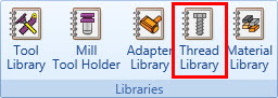
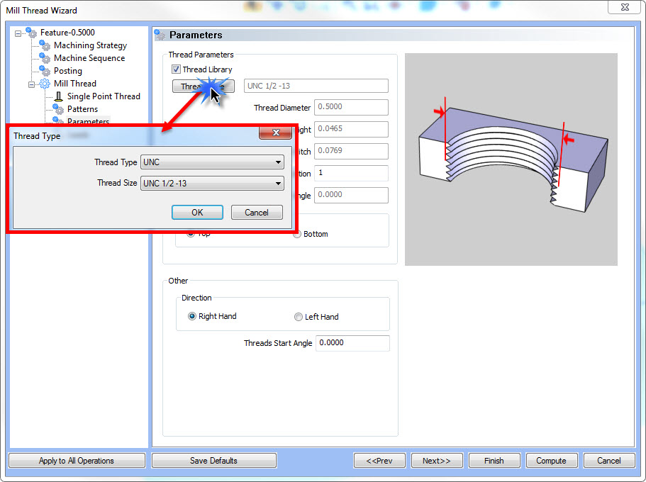
The first place I would start at is the thread library.
BobCAD comes preinstalled with many standard thread types.
It’s easy to add more size and make adjustments to the Major, Minor, Pitch, Pre Drill Sizes and more.
Recommendation Before You Start Thread Milling or Tapping Any Holes in BobCAD
Your first step would be to take a look at the thread library and add to or update, based on the types of threads you want to machine.
What Is The Thread Library?
The thread library is a library/table of thread types, sizes and settings. It’s used for both tapping holes and thread milling.
You’ll use the thread library to automatically call setting specific to tapping holes or thread milling.
- Major Diameter
- Minor Diameter
- Pitch
- Thread Angle
- Taper Angle
- Pre Drill Size
Now that you understand what the thread library is used for, your next step in this process is setting up your tools.
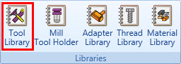
Tool Setup
Although BobCAD does come preinstalled with many standard thread mill tool sizes, it’s recommended that you add your own thread mills and settings to match the settings from your tooling supplier.
BobCAD has 2 tool categories for thread milling: Single Point and Multi-Point tools.
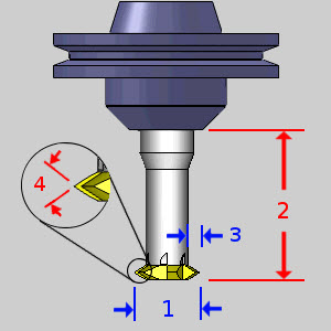
- Diameter
- Number of flutes
- Protrusion Length
- Pitch
- Thread Height
- Thread Angle
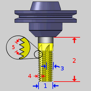
- Diameter
- Flute Length
- Overall Length
- Number of Flutes
- Protrusion Length
- Taper Angle
- Pitch
- Thread Height
- Thread Angle
At this point, you should understand that you can update BobCAD’s thread library to add more thread sizes and settings to match the kind of threads you want to manufacture.
At the same time you also understand that you can add to / update the tool library to match your tools settings provided by your tool supplier.
Now it’s time to talk about geometry selection and the role it plays with both tapping holes and thread milling.
Geometry Selection
If you are going to create an ARC for the hole locations when tapping holes, it’s recommended that the hole size you create be the minor diameter or the pre drill size.
It’s not necessary to select an ARC with the proper size.
By using the tap feature from the CAM tree, you’ll be presented with an option to choose a thread size from the wizard.
The sizes presented to you are based on the thread library.

The same holds true when it comes to thread milling.
For inside thread milling, you would draw and select the minor diameter.
The thread milling wizard will be presented with an option to choose a thread size from the thread library.
Selecting a thread size will pre-load Major, Minor, Pitch, etc.
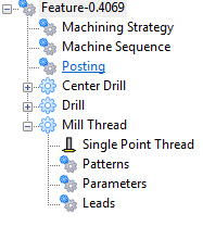
When it comes to thread milling the selected geometry is important to “process” for the hole prep.
- Center Drill
- Drill
- Chamfer Drill
- Chamfer Mill
- Ream
- Bore
- Profile Rough
- Profile Finish
The selected geometry is used to drive these operations.
If you’re drilling the hole, the selected geometry size would be used to call the drill size.
If you used a pocket or a profile ramp, the selected geometry would also be used to drive the operation.
Since we are currently working on an inside thread, we would draw and use the minor diameter as our reference geometry.
If we are working on an outside thread, we would use the major diameter as our driving geometry for the prep operation.
Pro Tip: Once you’ve programmed and tested the results of a thread milling feature, you can store and reused feature settings for future projects in one of the following ways.
- Save and load feature
- User Defined Template
- Job Tree Template
All of these methods will store feature information to be used on future projects.
Users can select a point location, or any ARC if you are reusing either a machining feature, a user defined template or a job tree template.
The software will use the selected geometry for it’s X-Y location only.
All other settings will come from the saved process.
Process
Now let’s talk about process.
We now have a good understanding about the thread library, setting up tools, geometry selection and the role the thread library plays.
Let’s take a look at some of the toolpath settings and options you can use when thread milling.
From inside the Mill Thread Wizard, you use patterns, parameters and leads to define the machining process.
Using the patterns tab you can adjust top-down or bottom-up cutting.
It also defined inside or outside threads types.

If you want to “walk into” the thread you can use side roughing.
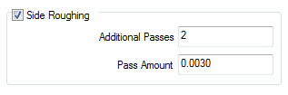
Pro Tip: Adding additional passes with no pass amount will produce spring passes.
Patterns is also used to set your compensation method.
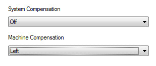
Pro Tip: In most cases, you’ll want to run machine compensation allowing you to adjust the thread height / fit at the control by adjusting your D value.
Using the Parameters tab to thread information from the thread library, you can also adjust the thread diameter pitch and number of teeth you’re using with multi teeth thread tools.
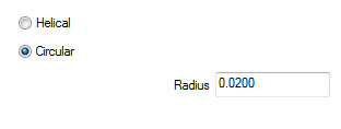
Using the leads tab, you can adjust the lead in/out style (Helical or Circular) and the radius size of the lead in.
Keep in mind that all of the wizard default setting can be customized and saved to a template.
Wizard templates are new to the V32 and users like you can save defaults settings of their choice.
To watch a detailed step-by-step process, join the BobCAD After Dark Facebook Group by clicking the link below:
https://www.facebook.com/groups/bobcadafterdark/
We host weekly live videos on Tuesdays and Thursdays from 12:00 PM ET to 1:00 PM ET.
Look forward to seeing you there.

BobCAD-CAM has provided CAD-CAM CNC Software products to the global manufacturing industry for over 30 years. BobCAD-CAM software can be found to increase CNC productivity for many applications in aerospace, automotive, production manufacturing, mold making, general machining, woodworking as well as the medical manufacturing industry, consumer products, musical instruments, custom fabrication, defense industry and many others due to the products ability to automatically generate NC programming code for such a wide variety of CNC controllers. BobCAD-CAM software is also found in educational institutions throughout the world as well as independent hobby home use. Products include machining technology for 2, 3, 4 & 5 Axis CNC Milling, Routing, Waterjet, Plasma and Laser machines as well as 2 Axis CNC Lathe. BobCAD-CAM is modular allowing shops to start off at a reduced technology level and add technology as it is needed including an add-on, BobART, for artistic machining. Unique technology includes adaptive high-speed machining multiaxis milling and routing which is a first in the world of CAD-CAM software. BobCAD-CAM also provides a variety of quality training products that include regional and online training classes or private sessions tailored to specific applications. Professional certification and multi-tiered support solutions are available. Contact BobCAD-CAM directly for more information at 877-262-2231 or 727-442-3554.


Leave a Reply