 CAD-CAM software provides advantages for simple and complex hole processing and CNC machining. CNC Shops throughout every branch of manufacturing rely on programming automation for hole processing-drilling. While many hole drilling scenarios are simple some performed on manual machinery and drill presses, CAD-CAM software is still holding strong when it comes to processing and machining holes.
Common CAD-CAM machine cycles for hole making include:
– Center Drill
– Hole
– Tap
– Rolled Tap
– Bore
– Ream
– Counter Bore
– Counter Bore Tap
– Counter Bore Rolled Tap
– Counter Bore Ream
Some CAD-CAM software products will list them differently than others. Essentially, by navigating to the machine setup feature, you will have access to all of the 2, 3, 4 and 5 Axis machining strategies or features depending on the software.
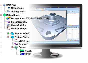
These would be provided as hole making features in a CAD-CAM product that should be accessible within a CAM Job Tree. The “Job Tree” will be the place in the software interface that all machining features are located along with posting, tools, materials, machine setup features and more. This is the centralized command center for creating the correct toolpath and NC program that you will send to the machine tool.
What are “Tool Pattern” Hole Processing Cycles in CAD-CAM?
CAD-CAM software products will sometimes provide what are known as “tool patterns” for machining features where more than one tool can be used in an operation. For example, a basic hole drilling features can be created using a center drill and a drill, with or without a chamfer as a third action to be completed in the operation. The tool pattern setting should be available on a per-part basis or as a global setting. Once again, “tool pattern” functionality controls the order of operations for all supported milling features that a CAD-CAM system offers. All changes that are made in the pattern control dialog box will generally affect the current part (loaded into the software) only and are not applied to any other parts unless the global settings are used. Then these tool patterns will be affected for all part programs when called for. CAD-CAM software allows the user to define these tool patterns to create efficient programs way faster than by hand.
Continue reading the complete whitepaper by clicking the link below…


Leave a Reply