When it comes to 3D part programming or really any part programming, controlling where the tool is cutting or not cutting is vastly important. This one topic, in many ways, determines the success or frustration you’ll have on your current or future project. Let’s take a look at some of the options you have at your disposal to control your toolpath in 3D.
Boundary Control
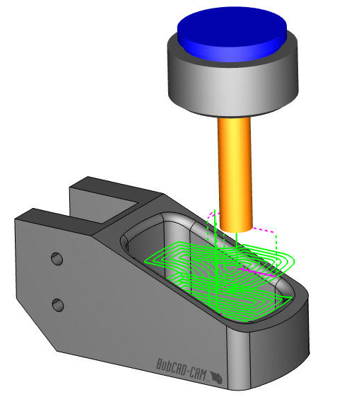
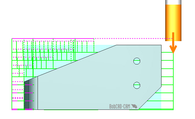
When using a boundary, users can limit where toolpath is created. Boundaries are a simple and easy way to control where the toolpath is created on your part model. Consider the following statement: Boundary control is typically used for X,Y limits. Just because you’ve set up a boundary, doesn’t mean the tool won’t cut too far in Z.
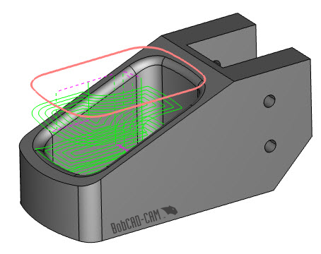
Another thing to consider: When using a boundary, the tool will typically plunge/ramp into the stock VS starting off the stock and working its way in.
What types of geometry can you use for a boundary? 2D wireframe is the most common, but users can also pick surface edges and 3D wireframe to control where toolpath is or isn’t created.
Top & Bottom of Job
If you need to control where you toolpath is cutting in Z, then top and bottom of job are where you will need to look. This setting is found on the parameters page of your 3D toolpath.
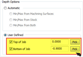
Users can pick or enter a starting point and ending point for their 3D toolpaths. This powerful feature is super simple to use. Just pick or enter the start of cutting “ Top of Job” value & pick or enter the end of cutting or “Bottom of Job” Value. Using user-defined top and bottom of job, users can define the Z extents used for the specific 3D toolpath being set up.
Subscribe to BobCAD-CAM's CNC Software Blog
Join your fellow manufacturers! Get BobCAD-CAM’s latest CAD-CAM articles straight to your inbox. Enter your email below:Stock & Operation Stock
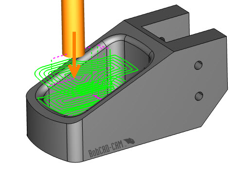
When it comes to 3D toolpaths, some are stock aware. This means the software “sees” the stock and when toolpaths are created they are based on where the stock is. This is one of the reasons when setting up a job that you’ll need to run the stock wizard to define your stock geometry.
One of the best features of stock aware toolpath is they allow the tool to start off of the material, working its way in VS plunging into the material.
Using stock aware toolpath with operation stock gives users more control over where their toolpath will be created in 3D. Best practice for in-process parts where prior operations have removed material.
Using operation stock in your 4 axis part programming allows you to tell the software what material you want to target with your toolpath. This one feature gives users the control needed to be more efficient.
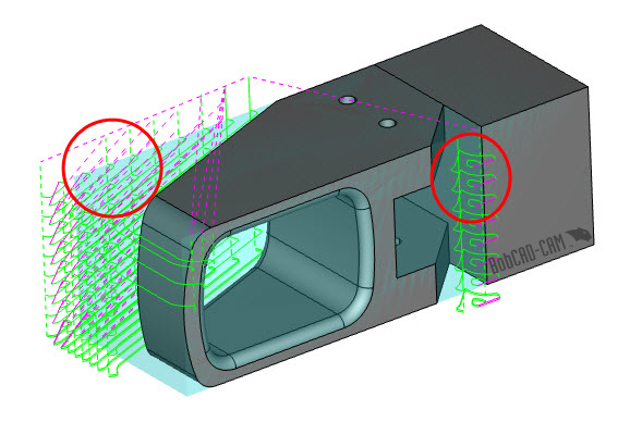
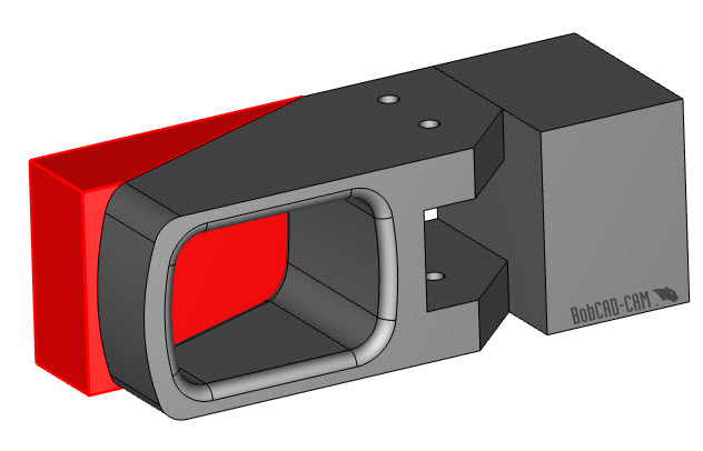
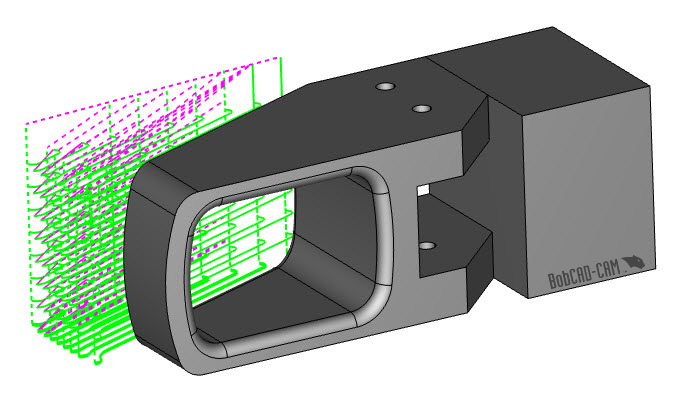
Like in this example, were toolpath is created on the front and back side of this part. Using operation stock, we can target just the material on the back side of this part and still have the benefit of the tool plunging off the material.
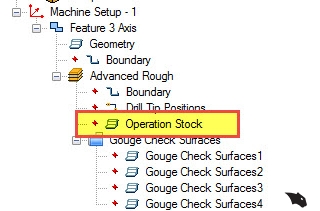
Create a solid model that represents what material you want to target and select it as your operation stock.
When you recompute your toolpath, it will only be created where the operation stock is located.
Operation stock is available for most of the Mill Professional toolpaths. Operation stock is selected for the operations, allowing you to provide stock geometry boundaries specific to the feature you are machining at that time. Your job tree can utilize multiple operation stock selections, allowing users to define toolpath and stock conditions for their in-process programming.
To learn more about using operation stock when you part program, download a demo.

You’re one click away from subscribing to BobCAD’s YouTube channel. Click the link below for tips, how-tos and much more!


Leave a Reply