 Recently on one of our BobCAD Facebook groups, a member posted this question. “Dumb question of the day. What is the difference between ‘workpiece’ and ‘geometry’? Why is there a boundary before the first machine operation?” Now, as you all know, there are no dumb questions when it comes to learning more about your craft and this will almost certainly help another person possibly to shy to ask. Let’s dive right into it!
Workpiece vs Geometry
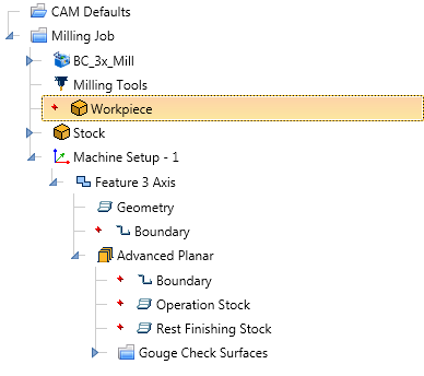
Workpiece selection is used for simulation. The “workpiece” is considered your part geometry in simulation. Users can select a workpiece in the CAM Tree to tell the software what solids to pass to simulation.
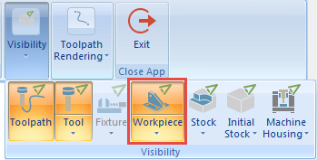
Users can toggle the visibility of the workpiece on or off in simulation to help better understand how their part is being machined.
Do you have to select workpiece geometry?
No. If no workpiece models are selected, any visible model in the CAD space when launching simulation will be considered the workpiece.
Why is there a workpiece selection?
This gives users the ability to select which models will be passed to simulation without having to “hide” models they don’t want to be passed.
As an example, if you are working on a part file that has multiple solid bodies, and they are visible in the CAD window when you launch simulation, all of the bodies will be passed and considered the workpiece.
The user could use the workpiece selection to define which solid bodies would be passed to simulation without the need to blank out the solids they don’t want to be passed to simulation before launching.
Geometry Selection
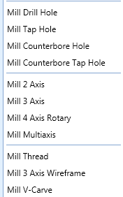
BobCAD is a feature-based CAM software. No, this doesn’t mean the software automatically programs your parts. What it means is that when you create toolpath, it’s based on creating a machining feature. Users choose from machining features for drilling; 2D or 3D
Subscribe to BobCAD-CAM's CNC Software Blog
Join your fellow manufacturers! Get BobCAD-CAM’s latest CAD-CAM articles straight to your inbox. Enter your email below:Each one of these features will start a machining wizard. The machining wizard is used to define the machining process that will be applied to your geometry selection. Each wizard has specific features and options for the type of feature you’ve picked.

Geometry selection within a feature is used to tell the software what geometry you want the toolpath applied to.
Unlike workpiece selection, which is only used to define which models are being passed to simulation.
So, geometry selection is what geometry you want toolpath applied to, whereas workpiece selection is used to define what solid bodies are being passed to simulation.
Feature 3 Axis Boundary Options
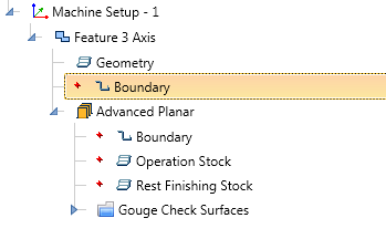
When you load a 3 axis machining feature, you’ll notice a top-level boundary for the feature & you’ll notice an operation level boundary. Why?
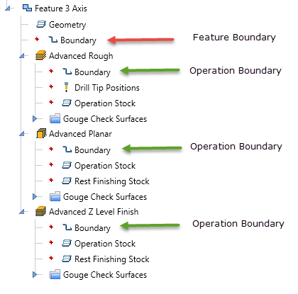
The feature-level boundary is used to define 1 boundary for all the machining operations. Keep in mind that using DMS (dynamic machining strategies), you can load multiple operations for a single feature. Each operation has its open boundary selection. This allows users to choose a top-level boundary that’s applied to all operations, with the control to use an operation level boundary that’s specific to its operation.
If your machining feature only has 1 operation, then the boundary is redundant. If your feature has multiple operations then each operation has an option for its own unique boundary. There you have it! Make sure to subscribe to this blog using the form above for more great CAD-CAM Quick Tips like this one!

Start your Test Drive.
Have questions? Call us at 877-838-1275.


Leave a Reply