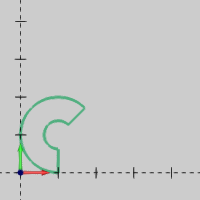
This section shows the results of changing the Position and Orientation parameters that apply to all shapes.
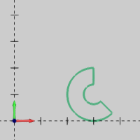
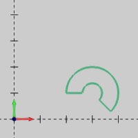
A cut ring shape at the default position and orientation is shown first.
|
Position change: X = 2.000 and Y= 2.000
 |
Notice the location of the shape in reference to the new origin at X2.000 Y2.000.
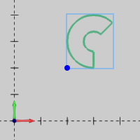 |
For this shape, the origin is the lower-left corner of a bounding box drawn around the entity. This is the case for most shapes, but be aware that some shapes use the arc center as the origin.
TIP: When using the Position and Orientation parameters, think of a coordinate system placed at the origin of the shape, with the X-axis and Y-axis of the origin being parallel to the X-axis and Y-axis of the WCS. This makes it easier to understand the expected results when modifying the Position and Orientation parameters. (The mirror and rotation options are in reference to the coordinate system at the origin of the shape, not the WCS.)
 |
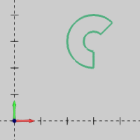
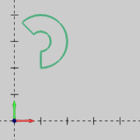
The current position and orientation of the shape is shown first.
|
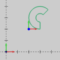
Flip X
 |
Notice that the shape is mirrored across the X-axis of the shape origin as explained in the previous tip.
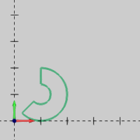
Flip Y
 |
Again, the shape is mirrored across the Y-axis of the shape origin, not the WCS (CAD origin).
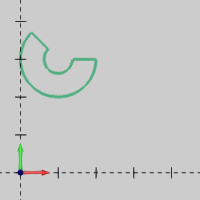
Flip X and Flip Y
 |
The shape before rotation is shown first.
|
Rotation Angle = 90.000
 |
Rotation Angle = 270.000
 |
The previous images show that the Rotation Angle parameter rotates the defined shape around the origin (or Z-axis) of the shape.