In this Topic Show
The Dimension functions are used to measure geometry and place a dimension in the graphics area. The Dimension text has a leader line that points to the witness lines. The witness lines show the measured distance, so they extend from the points of measurement (on the entity) to the leader line of the dimension text.
The Dimension text and appearance can be customized to your preferences. The Dimension types are each designed for a specific purpose, such as taking horizontal dimensions and placing the dimension text vertically (X-Ordinate).
NOTE: Depending on the number of fonts installed on your system, the Dimension parameters may take a few moments to load the first time that you select a Dimension function (in any file).
All of the Dimension functions are located in the Dimension menu. You
can also access all of the same Dimensions using the Drafting toolbar.
When you select a Dimension function, the parameters display in the ![]() Data Entry Manager.
Data Entry Manager.
TIP: You can read the prompt line of the Status Bar, at the bottom-left side of the user interface, to guide you while creating dimensions.
Selectable entity types for dimensions are lines, arcs, splines, and the edges of surfaces or solids.
Selection Limitations
Angle - lines only
There are two ways to select entities:
Individual Picking
You click an entity to select the closest snap point of the entity. You can also press and hold down Shift, and click an entity to view the snap points before selecting them.
Window Picking
You window pick entities by pressing and holding down Shift while dragging the mouse to create a selection window. Window picking measures the total distance of each entity and automatically places the dimension. The edges of solids and surfaces must be selected individually.
The following is a brief description of each dimension type. The Dimension parameters are shared for most dimension types and explained after these descriptions.
Horizontal is used to dimension the distance of, or between, entities as measured along the X-axis. The dimension text is parallel to the X-axis. How to Create Horizontal Dimensions
Vertical is used to dimension the distance of, or between, entities as measured along the Y-axis. The dimension text is parallel to the Y-axis. How to Create Vertical Dimensions
Other Distance dimensions the absolute distance between any two snap points. How to Create Dimensions Using Other Distance
Angle dimensions the angle between two lines. You select each line in a counter-clockwise direction. If the lines are selected in a clockwise direction, the dimension reflects the reverse angle (or conjugate angle). How to Create an Angular Dimension
Radius dimensions the radius of an arc (or the distance from the arc center to the edge of the arc). You can window pick or individual pick arcs only for this dimension type. How to Create Radius Dimensions
To use Auto, you select multiple entities, and the software automatically creates the dimensions based on the entity type and orientation. You can select single entities, or hold Shift and drag a window to select and dimension more than one entity at one time. How to Create Dimensions Automatically
X-Ordinate dimensions a distance along the X-axis, and places the text parallel to the Y-axis. How to Create X-Ordinate Dimensions
Y-Ordinate dimensions a distance along the Y-axis, and places the text parallel to the X-axis. How to Create Y-Ordinate Dimensions
Chain Dimension is used to select the end of an existing dimension as the first snap point for the next dimension. You then select more snap points to continue creating chained (contiguous) dimensions. (Each new selection that you make sets that dimension as the current chain dimension.) All dimensions that you create using Chain Dimension are aligned with the first dimension and use the same parameters as the first dimension. How to Create Chained Dimensions
Because Chain only works with an existing dimension, Cancel is the only Data Entry parameter available.
Reference Dimension uses the start of an existing dimension as the reference for the next dimension. This creates dimensions that report the distance from the beginning of a reference dimension to another snap location within a series of contiguous entities. How to Create Reference Dimensions
Point dimensions the XYZ coordinate of any point. You can select point geometry or select the snap point of any other geometry type. When selecting wireframe entities, the closest snap point of the entity is dimensioned. How to Create Point Dimensions
Move is used to change the location of an existing dimension. You click the dimension to move, drag it to the new location, and click to place the dimension. How to Move Existing Dimensions
Because Move only affects existing dimensions, Cancel is the only Data Entry parameter available.
Align Horizontal is used to select an existing dimension and align other existing dimensions to the same Y-axis position. This can only by used with Horizontal, Vertical or Other Distance. To use the function, first click the dimension to use as the alignment reference. Then click any number of dimensions to align to the first dimension. Each dimension is moved when you click it. To finish the function, click Cancel. How to Align Dimensions Horizontally
Because Align Horizontal only affects existing dimensions, Cancel is the only Data Entry parameter available.
Align Vertical is used to select an existing dimension and align other existing dimensions to the same X-axis position. This can only by used with Horizontal, Vertical or Other Distance. To use the function, first click the dimension to use as the alignment reference. Then click any number of dimensions to align to the first dimension. Each dimension is moved when you click it. To finish the function, click Cancel. How to Align Dimensions Vertically
Because Align Vertical only affects existing dimensions, Cancel is the only Data Entry parameter available.
Cross Hatch is used to fill a contour, or closed chain of entities, with repeating line segments. This can be a hatch (single set of parallel fill lines) or it can be cross hatch (double set of parallel fill lines perpendicular to each other). How to Use Cross Hatch
View the Cross Hatch Data Entry tab
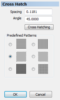
Predefined Patterns
The Predefined Patterns are used together with the Spacing and Angle values. The top four patterns all use a single set of fill lines with Angle values of 0, 45, 90, and 135 degrees. Notice that the bottom two patterns are the Cross Hatch patterns set at 0 and 45 degrees. Selecting one of these options automatically selects Cross Hatching.
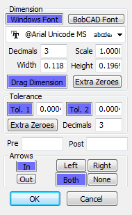
View the Dimensions Data Entry tab
You must first decide the font type used for the dimension text. Select either Windows Font or BobCAD Font. The default font for the selected type is displayed in the Font box. Click the arrow on the right side of the Font box to display a list of available fonts. Select the desired font from the list.
Decimals - sets the number of decimal places, or digits after the decimal point, displayed in the dimension text. These are only displayed for values that aren't whole numbers, unless an Extra Zeroes value is set.
Scale - sets the scale of the measured dimension. A value of one means no scaling or 100 percent of the actual size of the entity. A value of 0.5 means that when you place a dimension on a line that is two units long, the dimension displays a value of one unit.
Width - type a value to set the width of the dimension text.
Height - type a value to set the height of the dimension text.
Drag Dimension
Off - after you select the dimension entities, the dimension is automatically placed in the graphics area.
On - after you select the dimension entities, you can drag the dimension and click to place it in the desired location.
TIP: When window picking entities to dimension (press and hold Shift and drag the mouse to select an area), Drag Dimension is disabled.
Extra Zeros
Off - when a dimension is placed that is a whole number, no decimal places are shown, regardless of the Decimals value.
On - when a dimension is placed that is a whole number, zeros are shown in the dimension. The number of zeros is set by the Decimals value (in the Dimension group).
The Tolerance group is used to display any needed tolerances in the dimension. When tolerances are set, the dimension is displayed with + or - values to represent the tolerances.
Tol. 1 - select this option to enable the Tolerance 1 box and type a tolerance value that is displayed with the dimension.
Tol. 2 - is the same as Tol. 1 but provides a second tolerance value.
Extra Zeros
Off - no extra zeros are added to the tolerance value. The tolerance is displayed using the Tolerance value and the Decimals value. The Decimals value is only used when the decimal values themselves are not zero. For example, if Tolerance = 1.000, and Decimals = 3, the result is a display of 1, if you then change the Tolerance = 1.003, then it appears as 1.003.
On - adds extra zeros to the tolerance value using the Decimals value. For example: if Tolerance = 1.004, and Decimals = 2, the tolerance is displayed as 1.00.
Decimals - sets the number of decimal places, or digits after the decimal point, displayed in the tolerance text. These are only displayed for values that aren't whole numbers, unless an Extra Zeroes value is set. For example, if Tolerance = 0.004, with Decimals = 2, the Tolerance is displayed as 0, unless an Extra Zeroes value is set.
Pre - type text in this box and it is placed before the displayed dimension text.
Post - type text in this box and it is placed after the displayed dimension text.
When a dimension is placed automatically (Drag Dimension off), witness lines are drawn, from the selected entity points, to the location of the dimension. These lines show the distance that is being measured. The Dimension text is placed in between the witness lines. Two more lines with arrows, or the leader lines, extend from the dimension text and point to the witness lines. The Arrows group controls the location and direction of these leader line arrows in relation to the witness lines.
Select one of the following options:
In - places the arrows on the inside of the witness lines.
Out - places the arrows on the outside of the witness lines.
The following four options control which arrows are used. When creating dimensions by selecting snap points, Left refers to the first point, and Right refers to the second point:
Left - one arrow points to the left witness line.
Right - one arrow points to the right witness line.
Both - two arrows are used, with one pointing to each witness line.
None - no arrows are used.
TIP: The default values for Dimensions are set in the Preferences menu, under Settings Part and Settings Default. There are various other parameters in these dialog boxes that affect the appearance and layout of the Dimensions.