In this Topic Show
This topic describes how to create and place dimensions for parts in the graphics area. To learn about all of the settings used with Dimensions, view the Dimensions. The default settings used when creating Dimensions can be customized using the Settings Default (for all new files) or Settings Part (for the current file) dialog boxes. If you only want to obtain the measurements of one or two entities without placing a dimension in the graphics area, you use the Measure functions (Utilities menu).
The process used to create dimensions is the same for most Dimension types. The main difference between the various Dimension functions is the direction of the measurement and the direction of the Dimension text. This section explains the general process, which can be applied to most of the Dimension types. After this explanation, specific examples are shown with images for each dimension type.
1 To select the Dimension type, in the Dimension menu, click the desired dimension.
You can also click an icon on the Drafting toolbar.
The available settings are displayed in the
![]() Data Entry
tab of the Data-CAM Tree Manager.
Data Entry
tab of the Data-CAM Tree Manager.
2 Make any necessary changes to the Data Entry Parameters.
This includes the parameters (size, font, and other formatting) of the Dimension text, arrows, and witness lines. (The default settings are defined in the system Preferences.)
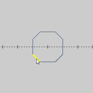
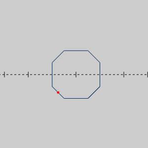
3 Click an entity near the first point of measurement.
The selected snap point changes color to show that it is selected.
4 Click an entity near the second point of measurement.
The dimension preview is displayed.
5 To place the dimension, point to and click the desired location in the graphics area.
This method uses the default setting of Drag Dimension.
When Drag Dimension is turned off, the dimension is automatically placed after making the second selection.
The only Dimension functions that do not follow this procedure are Move, Align Horizontal, Align Vertical, and Cross Hatch. These functions are explained later in this topic.
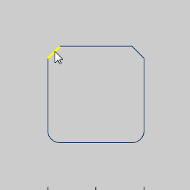
TIP: When selecting entities to Dimension, press and hold Shift and click an entity to show the available snap points. You can then click a snap point to use for the dimension. Alternatively, when you click an entity without showing the snap points first, the software automatically selects the closest snap point of the entity. (Lines, for example, always have three snap points: start, end, and center.)
The following examples explain the process and any important notes for creating dimensions. You can apply this information to your own parts, or if needed, view the CAD_Tutorials to learn how to create geometry to use with these examples.
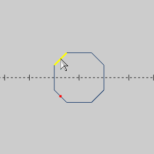
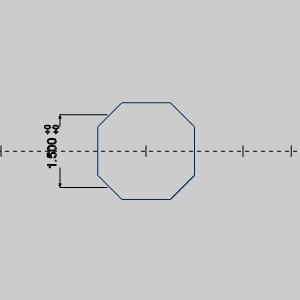
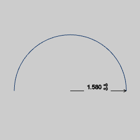
Horizontal Dimension measures a distance along the X-axis and places the text along the X-axis.
1 To start the function, in the Dimension menu, click Horizontal.
2 Click an entity near the desired point of measurement.
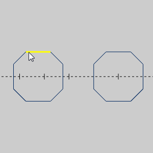
The closest snap point of the entity changes color to show that it is selected.
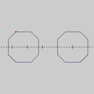
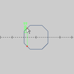
3 Click near the second desired point of measurement.
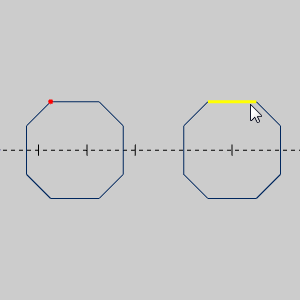
Once the second dimension point is selected, the dimension preview appears.
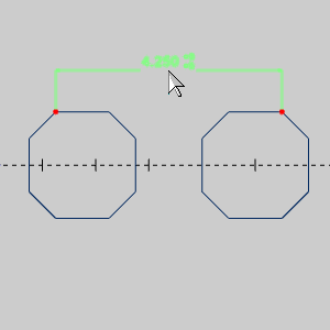
4 To place the dimension in the graphics area, point to and click the desired location.
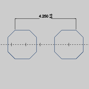
When using Drag Dimension, you can drag the dimension to any location.
The following image shows the dimension placed off to the side.
Vertical Dimension measures a distance along the Y-axis and places the text along the Y-axis.
1 In the Dimension menu, click Vertical.
2 Click an entity near the desired point of measurement.
3 Click near the second desired point of measurement.
Once the second dimension point is selected, the dimension preview appears.
4 To place the dimension in the graphics area, point to and click the desired location.
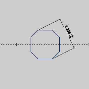
Other Distance Dimension measures a distance between any two points and places the text parallel to the line created between the two points.
1 In the Dimension menu, click Other Distance.
2 Click an entity near the desired point of measurement.
3 Click the second point of measurement.
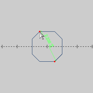
The dimension preview is displayed.
4 To place the dimension, point to and click the desired location.
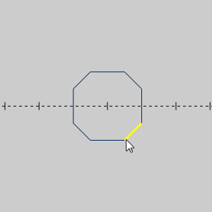
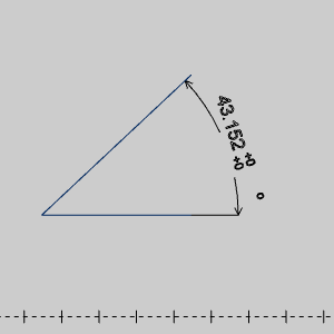
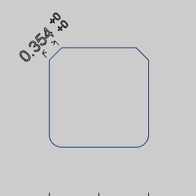
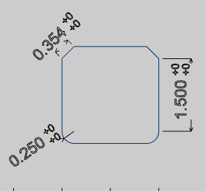
Angle Dimension measures the angle between two lines and places the text anywhere along the radius of the witness line.
IMPORTANT: When creating an angular dimension, you must select the entities in a counter-clockwise direction in order to create the proper angle. If you select the entities in a clockwise direction, the angle created is the reverse (or conjugate) angle.
1 In the Dimension menu, click Angle.
2 Click the first line for which the dimension is created.
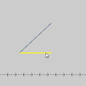
3 Click the second line.
The dimension preview is displayed.
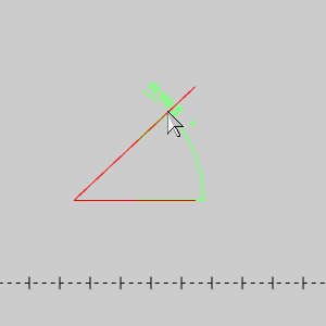
4 To place the dimension, point to and click the desired location.
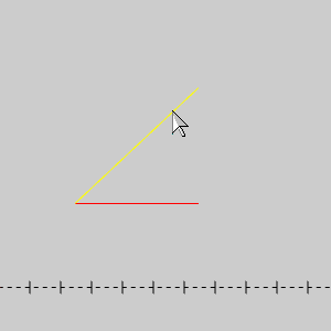
The following image shows the result that is created when the entities are selected in the opposite order from that shown previously.
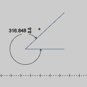
This dimensions the opposite angle.
Radius Dimension measures the radius of an arc and places the text anywhere along the witness line.
1 In the Dimension menu, click Radius.
2 Click the arc for which the dimension is created.
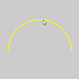
The dimension preview is displayed.
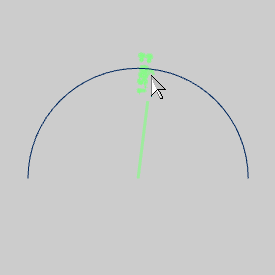
3 To place the dimension, point to and click the desired location.
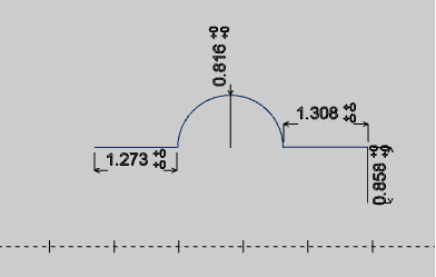
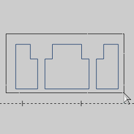
Auto Dimension can be used in two ways: single selection or multiple selection. For single entity selections, Auto automatically changes the dimension type based on the orientation of each entity. Auto also automatically creates dimensions for multiple entity selections. To select multiple entities, press and hold Shift while dragging the mouse to create a selection window. All dimensions are automatically created based on the entity type and orientation.
1 In the Dimension menu, click Auto.
2 Click the first entity to dimension.
3 The total length of the selected entity is dimensioned with one click.
The Dimension preview is displayed.
4 Drag the dimension to the desired location and click to place the dimension.
5 You can repeat this process for each entity type to be dimensioned.
1 In the Dimension menu, click Auto.
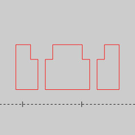
2 To dimension multiple entities automatically all at once, press and hold Shift and drag and window around the entities.
When you release the mouse button (before releasing Shift), the entities change color to show that they are selected.
3 Once the selections are made, press the Spacebar to accept the geometry selections.
All selected entities are automatically dimensioned based on the entity type and direction.
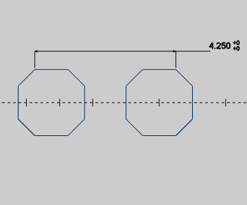
X-Ordinate Dimension measures a distance along the X-axis and places the text along (or parallel to) the Y-axis. You can follow the same procedure as shown in the Horizontal Dimension example. An example image of the result is shown next.


Y-Ordinate Dimension measures a distance along the Y-axis and place the text along (or parallel to) the X-axis. You can follow the same procedure as shown in the Vertical Dimension example. An example image of the result is shown next.


Chain Dimension uses an existing linear or angular dimension as the starting point when creating a contiguous chain of dimensions. All dimensions that you create using Chain Dimension are aligned with the first dimension and use the same parameters as the first dimension.
1 After creating a linear or angular dimension, in the Dimension menu, click Chain.
The Dimension parameters are displayed in
the  Data Entry tab.
2 In the graphics area, click the existing dimension.

3 To define the next dimension, click an entity near the location of the next dimension.

The next dimension is automatically created when you select a snap point.

Notice that the dimension just created remains selected (as shown in red).
4 To define the next dimension, click an entity near the location of the next dimension.


You can continue to create as many dimensions as needed by selecting a snap point for each following dimension.
5 For the last dimension of this example, press and hold Shift while clicking an entity to show the available snap points.

6 Once the snap points are displayed, click the snap point to use for the dimension.

When you click the snap point, the dimension is created and placed.

7 To finish the function, in the Data Entry tab, click Cancel.
Reference Dimension uses an existing dimension as a reference for one or more following dimensions. All dimensions that are created from the Reference dimension use the first point that was selected when creating the reference dimension. After selecting the Reference dimension, each selection creates a dimension using the Reference dimension starting point.
You must have an existing linear or angular dimension to use as the Reference Dimension.
1 In the Dimension menu, click Reference.
The Reference Dimension parameters are displayed
in the Data Entry tab.
2 Click the existing dimension, all other dimensions that you create use the start of this dimension as the reference (the snap point you selected first when creating the Reference Dimension).

TIP: The parameters that are defined for the original (Reference) dimension, are used for the dimensions that are created using Reference Dimension. Be sure to define the dimension parameters properly for the Reference Dimension. You can't change the parameters separately for the dimensions that are created from the Reference Dimension.
3 Now that the Reference Dimension is defined, click an entity near the snap point of the next dimension.


4 Select the next point to create the next dimension.


5 Repeat the same process for all dimensions as needed.


6 To finish the function, in the Data Entry tab, click Cancel.
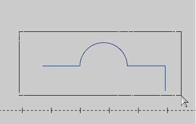
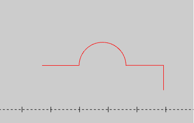
NOTE: When creating a dimension that is used as the Reference dimension, the order of selection defines how the other dimensions are created. The first point that is selected defines the starting point for all subsequent dimensions. In this example, the left arc was selected first, and the right arc was selected second. To create the opposite result, when creating the Reference dimension, select the arc on the right, and then select the arc on the left.
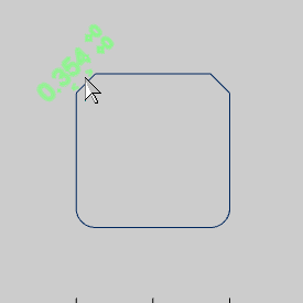
Point Dimension measures the XYZ coordinate value of any point and places the text along (or parallel to) the X-axis. You can create dimensions for points or the snap points of geometric entities.
1 To dimension a point, in the Dimension menu, click Point.
The Point Dimension parameters are displayed
in the Data Entry tab.
2 Make any necessary changes to the Data Entry parameters.
3 In the graphics area, click a point (this includes clicking a wireframe entity near the desired snap point).

4 When the dimension preview is displayed, point to the desired location and click to place the dimension.


5 To show the available snap points of wireframe entities, press and hold Shift and click the entity.


6 Click the snap point to dimension.

7 When the dimension preview is displayed, point to the desired location and click to place the dimension.

8 To finish the function, in the Data Entry tab, click Cancel.
Move Dimension is used to move an existing dimension text to a new location. This function is for existing dimensions only.
1 To move an existing dimension, in the Dimension menu, click Move.
Because move dimensions only moves an existing dimension, Cancel is the only parameter displayed in the Data Entry tab.
2 In the graphics area, click the dimension that you want to move.

The dimension changes to the Preview color to show that it is selected.

3 Drag the dimension to the desired location, and click to place the dimension.

4 You can repeat this process for any number of dimensions.
5 If you would like to align the remaining dimensions to the newly moved dimension, use Align Horizontal.
Align Horizontal is used to move existing dimensions to the same horizontal height (or Y-axis value). You first select the dimension to which the other dimensions are aligned, and then select all dimensions to move to the selected location.
1 In the Dimension menu, click Align Horizontal.
Because Align Horizontal only affects existing
dimensions, Cancel is the only parameter displayed in the Data Entry tab.
2 In the graphics area, select the dimension that is used as the reference location to which all other dimensions are aligned.

The dimension changes to the Selection color.

3 Select the first dimension that you want to align with the previous selection.

When you click the dimension, it is moved to the new location.

4 You can continue to select as many dimensions as needed to align to the first dimension.


5 To finish the function, in the Data Entry tab, click Cancel.
Align Vertical is used to move existing dimensions to the same vertical height (or X-axis value). You first select the dimension to which the other dimensions are aligned, and then select all dimensions to move to the selected location.
1 In the Dimension menu, click Align Vertical.
Because Align Vertical only affects existing
dimensions, Cancel is the only parameter displayed in the Data Entry tab.
2 In the graphics area, select the dimension that is used as the location to which all other dimensions are aligned.

The dimension changes to the selection color.

3 Select the first dimension that you want to align with the previous selection.

When you click the dimension, it is moved to the new location.

4 You can continue to select as many dimensions as needed to align to the first dimension.


5 To finish the function, in the Data Entry tab, click Cancel.
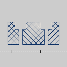
Cross Hatch is used to fill closed contours with a hatched or cross-hatched pattern of fill lines. Generally, you should define a closed shape in order to create a hatched pattern. You can still use Cross Hatch on open shapes, but the results may not be as expected (the software does not necessarily fill the open shape as if it were closed). You can always temporarily close an open shape to use Cross Hatch and then delete the extra entity afterwards. The entities created by the Cross Hatch function can also be selected and deleted after they are created.)
1 To fill an area with a hatch pattern, in the Dimension menu, click Cross Hatch.
The available parameters are displayed in
the ![]() Data Entry tab.
Data Entry tab.
2 Make any necessary changes to the Data Entry parameters (which are explained in the Cross Hatch topic).
For this example, Cross Hatching is selected.
3 In the Workspace, select the closed contours to be filled.
4 After selecting the geometry, press Spacebar to confirm the geometry selection.
The cross hatch pattern is applied to the inside of the selected entities.
The Dimension functions also work with solid and/or surface geometry, but you must select edges (not faces) as these geometry types only contain snap points at the intersection of faces or surfaces (vertices). You can dimension the distance between these snap points, but not radii or angles. For example, you can't create a radius dimension from a solid edge. You can always use Extract Edges to create wireframe from the solid and then dimension the wireframe. If you want to obtain other measurement types, such as volume, area, number of edges, faces, or vertices, you use the Measure One function.
This concludes the Dimension tutorials.