In this Topic Show
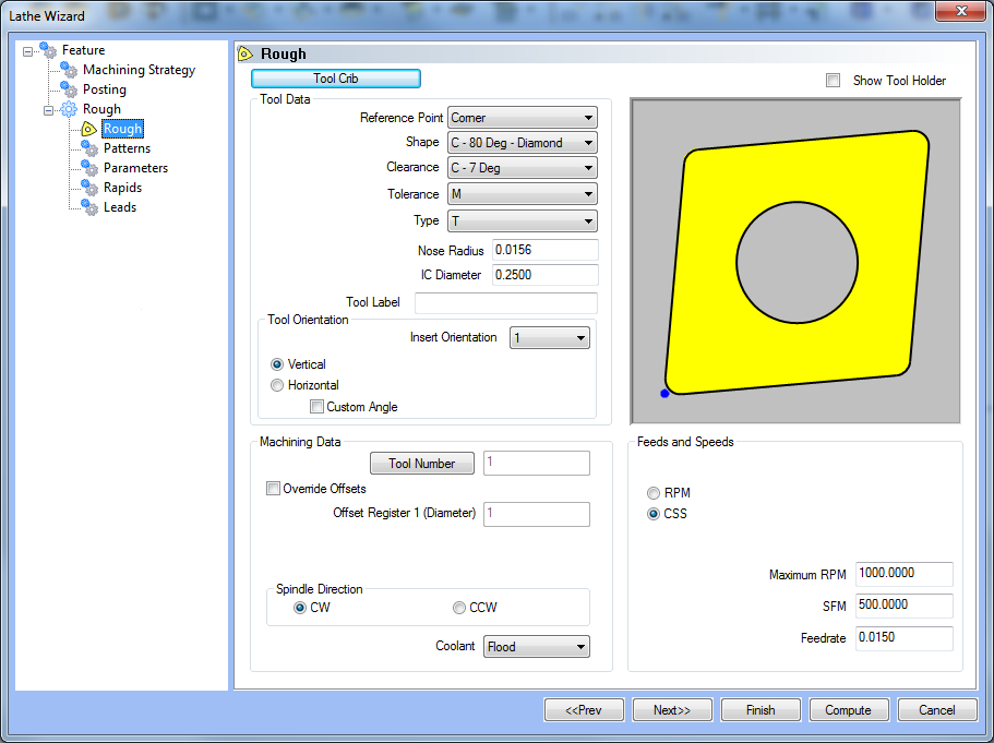
The Rough operation has several tools to choose from. Whether you use a Rough, Finish, Groove, or Boring tool, it is good practice to have all the tools for the job loaded into the Tool Crib at the start of the job. By this point, those tools should already be in the Tool Crib, and the system will have pulled appropriate tools for each operation from the Tool Crib. From this tool page, you can either, choose a different tool from the Tool Crib, go into the Tool Crib to add tools from your Tool Library, or enter tool specific data manually into the Tool Data Section of the page.
This page will also assist in assigning Tool Numbers and Offsets, Spindle Direction and Coolant options, as well as Speeds and Feeds.
Tool Crib - opens the Tool Crib for you to select a tool that you have already loaded for the job. Click to select a tool in the tools list, and click OK to assign the tool to the operation. (For Mill Turn jobs, view Mill Turn Tool Crib.)
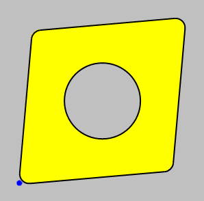
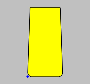
 Show Tool Holder - Selecting this
check box will alter the graphic to show the holder as well as the insert.
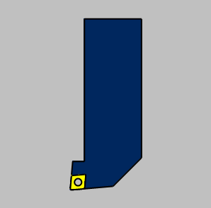
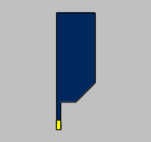
Show Tool Holder - Selecting this
check box will alter the graphic to show the holder as well as the insert.
|
|
||||||||||||
|
|
||||||||||||
Tool Data
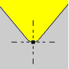
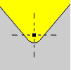
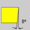
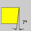
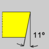
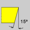
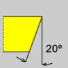
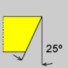
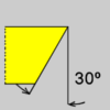
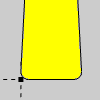
Tool Orientation
NOTE: The Orientation Number defines whether the cut is inside or outside of the geometry and the direction of cut and will be set for you based on the Feature Type and Region chosen in the Feature page. 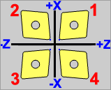
|
Tool Data
Tool Orientation
NOTE: The Orientation Number defines whether the cut is inside or outside of the geometry and the direction of cut and will be set for you based on the Feature Type and Region chosen in the Feature page. 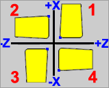
|
The Machining Data parameters change slightly depending on whether you are in a Turning job or Mill Turn job. All parameters are explained next.
Tool Number - opens the Assigned Tools dialog box for you to change the tool numbering.
For Mill Turn jobs, view the Assigned Tools for Mill Turn.
Override Offsets
Clear the Override Offsets check box to use the tool number to set the
Offset Register value.
 Select the Override Offsets check box to allow for manual editing of the
Offset Register value.
Select the Override Offsets check box to allow for manual editing of the
Offset Register value.
Offset Register 1 (Diameter) - sets the register on the machine that stores the diameter offset values for the tool.
Offset Register 2 (Height) - sets the register on the machine that stores the height offset values for the tool (Mill Turn jobs only).
Suffix Code - is an alphanumeric value used for the tool numbering for certain mill-turn machines, generally those with Mazak controllers (Mill Turn jobs only).
Spindle Direction
CW - outputs the command for clockwise rotation of the spindle.
CCW - outputs the command for counter-clockwise rotation of the spindle.
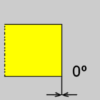
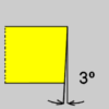
Tool Angle Control (Mill Turn only) - opens the Tool Angle Control dialog box for you to specify the rotation angles for both the milling head and lathe tool for the operation. This is used only for operations performed with a milling spindle/head and turning tool mounted to it.
Coolant - sets the coolant option for the operation. Select one of the following options: Off, Flood, Mist, Air, or Oil.
RPM - sets the feeds and speeds to revolutions per minute.
CSS - sets the feeds and speeds to a constant surface speed.
Maximum RPM - sets the limits of the spindle speed in the posted NC program.
Spindle RPM/SFM - sets the spindle speed for the feature in revolutions per minute or the surface feet per minute based on the selected RPM/CSS option.
Feedrate - sets the feedrate for the feature.
Once the Rough Tool variables have been set, click  to continue to the Roughing operations Patterns
page.
to continue to the Roughing operations Patterns
page.
 Rough Tool
 Groove Tool