Custom Chain
Custom Tool
In this Topic Show
This topic explains how to create custom milling or drilling tools (form tools) in BobCAD-CAM. The process of creating custom tools in BobCAD-CAM includes creating a wireframe profile of the tool that is revolved around the Y-axis of the WCS. You create solid entities to define the cutting portion of the tool and dashed entities to define the non-cutting portion of the tool. You then assign the geometry to the tool and define its parameters.
You can create custom tools for any milling or drilling tool type as well as lathe drilling tools. The custom tools can then be used for any milling or drilling operations that support the tool category in which the tool is made.
There are a few key points to creating the geometry for custom tools:
TIP: You can change the line style as needed while drawing each wireframe entity, or you can draw the entire shape first and use the Modify Entity commands to change the line style afterwards.
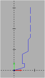
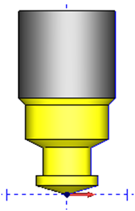
Custom Chain |
Custom Tool |
|
|
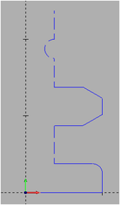
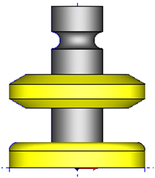
Custom Chain |
Custom Tool |
 |
 |
After defining the custom profile for a tool, you assign the geometry to the tool using the Create/Modify Tool dialog box that is accessed from the Tool Library.
1 In the CAM Tree, right-click CAM Defaults (or Mill Tools), and click Tool Library.
IMPORTANT: You cannot assign custom tool geometry when accessing the Tool Library from the CAM wizards.
2 Select a tool category on the left, such as Endmill Rough, to filter the tools list.
To create a new tool, click the Add button.
To modify an existing tool, select the tool in the tools list, and click Modify.
3 In the Create/Modify Tool dialog box (titled by the selected tool category), click the Assign Tool Geometry button.
TIP: After assigning custom tool geometry, the Assign Tool Geometry button changes to Remove Tool Geometry. You can use this button to remove the custom geometry and assign a new geometry profile.
4 In the graphics area,
click to select the custom chain, and click ![]() (OK)
to confirm the selection.
(OK)
to confirm the selection.
Note
that you can use chain selection (hold Shift and click an entity), or
you can window select the chain, but it is important that you only select
a single continuous chain of lines and/or arcs.
When you confirm the selection, the software returns you to the Create/Modify Tool dialog box for you to finish defining the tool. A preview of the custom tool displays on the right side of the dialog box. The software automatically sets some tool parameters based on the selected profile, but you must confirm all parameters.
6 Enter all tool parameters for the custom tool and click OK to finish.
The software automatically populates many of the tool parameters based on the custom geometry that you define, but there are two key points:
The software sets the tool parameters based on the custom tool chain you select as follows: