In this Topic Show
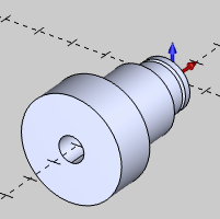
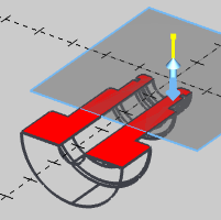
The Section View function is used to create a sectional view of solid geometry in the Workspace. This also includes the ability to create wireframe geometry by extracting the edges currently visible in the section view. When opening Section View, the solid model displays using wireframe and the Section View viewing plane displays. You can click the arrows in the center, or the edges of the viewing plane, to manually update the viewing plane position and orientation. Also, next to the arrows in the center of the viewing plane is the normal indicator, which represents the positive direction used for modifying the viewing plane parameters.
To open Section View, do one of the following:
In the View menu, click Section View.
On the View toolbar,
click the ![]() icon.
icon.
Right-click anywhere in the Workspace, point to Views and click Section View.
The parameters display in the ![]() Data Entry tab
of the Data-CAM Tree Manager.
Data Entry tab
of the Data-CAM Tree Manager.

You can select the viewing plane using one of the two following methods.
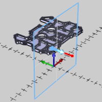
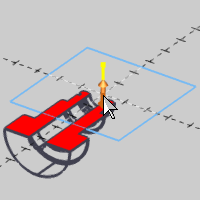
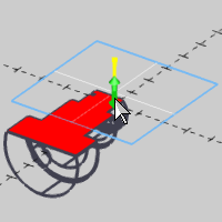
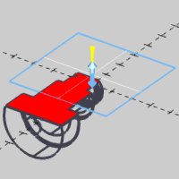
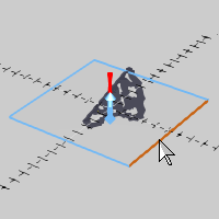
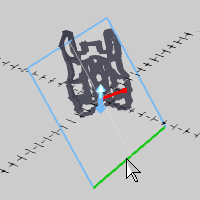
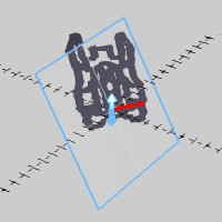
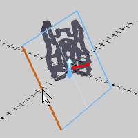
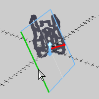
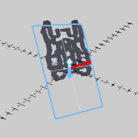
TIP: After using the section view handles to change the Distance or Rotation parameters, you can then update the values in the Data Entry Manager if needed.
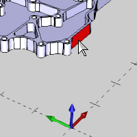
1 Open the function and select the viewing plane using either Pick a Surface or by selecting a UCS from the list.
2 Update the Distance and Rotation values using either Data Entry or by clicking the drag handles on the section view plane in the Workspace.
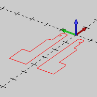
3 If you want to extract the visible edges and create wireframe geometry, click Generate Wireframe.
4 To reset the section view parameters to the selected UCS or surface, click Reset.
This is helpful if you want to create a sectional view for another solid.
5 To close the function, click Cancel.