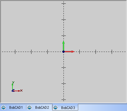
The graphics area, also known as the CAD window, is used to display any geometry that is created as well as any computed toolpaths. Each graphics area represents a file that is currently open. For each file that you open, there is a separate graphics area. By default, each graphics area has a tab at the bottom of the screen (in the Workbook), which you can click to view the selected graphics area.

In the bottom-left corner, the WCS (or world coordinate system) view indicator displays the positive directions of the X, Y, and Z axes. The WCS indicator is always in reference to the default Top (X/Y) UCS (selected in the UCS tab).
IMPORTANT: The default Top (X/Y) UCS (user coordinate system) is the WCS when working in BobCAD-CAM. When this help system references the WCS, it is referring to the Top (X/Y) UCS.
The UCS (user coordinate system) indicator in the center of the graphics area indicates the origin and axes directions for the Active UCS or drawing plane.
You right-click anywhere in the graphics area to access the Graphics Area Shortcut Menu with many useful commands, as well as the Entity Summary.
You view and select the geometry that you create in the graphics area. It is a good idea to become familiar with the mouse controls.
There are many default Keyboard Shortcuts that can help you to work fast. Note that you sometimes need to click in the graphics area, to give it key focus, first to use some of the commands.