


The UCS (user coordinate system) Manager is used to create and modify user coordinate systems. By default these include Top (X/Y), Front (X/Z), and Side (Y/Z). When you set a UCS as the active UCS, the coordinate system (not the WCS indicator) in the Workspace is updated to reflect the selected UCS. CAD geometry is created using the Active UCS.
TIP: The default Top (X/Y) UCS is the WCS or world coordinate system for BobCAD-CAM. The WCS coordinate system indicator displays in the lower-left corner of the Workspace, and it is always in reference to the Top (X/Y) UCS regardless of the Active UCS. When this Help system references the WCS, it is referring to the fixed Top (X/Y) UCS.
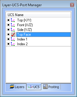
The default location of the Layer-UCS-Post Manager is the lower-left corner of the user interface. Click the UCS tab to access the UCS Manager.
You right-click anywhere in the UCS window, or the UCS name, to access a shortcut menu with the following commands.
When you click Add New UCS, the following parameters display in the Data Entry tab.
Direction 1 - sets the direction from the selected cylindrical face. If this doesn't create the desired result, select Direction 2, and select the face again.
Rotate - enables the X, Y, and Z boxes for you to type angle values, by which the UCS is rotated.
The Modify UCS dialog box contain many of the same parameters as the Create UCS dialog box. The difference being that the parameters are used to modify an existing UCS. Some of the parameters include an Absolute option for defining coordinate values from the WCS, instead of incremental values from the current position.
Absol. - sets the XYZ coordinates to absolute values, based on the WCS (world coordinate system).
Direction 1 - sets the direction from the selected cylindrical face. If this doesn't create the desired result, select Direction 2 and click the face again.
Rotate - enables the X, Y, and Z boxes for you to type angle values, by which the UCS is rotated. The values are incremental from the current location. To make these absolute values from the WCS, click Absol.
Absol. - sets the XYZ coordinates to absolute values, based on the WCS (world coordinate system).
The UCS that is selected when you open a CAD function determines the drawing plane.
To set the Active UCS, do one of the following:
 ).
).
When you set the active UCS, the UCS icon changes to the
 Active UCS icon.