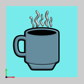
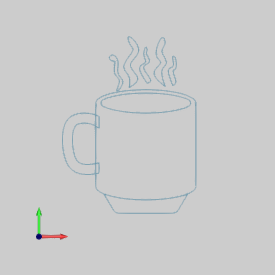
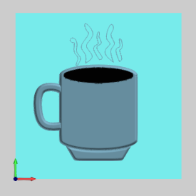
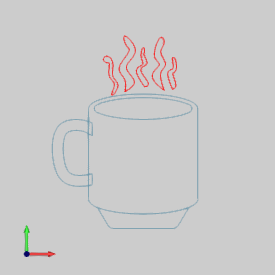
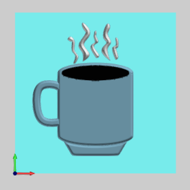
This topic explains how to create an Emboss Regular feature. This tutorial, in combination with the How to Create an Emboss Swept tutorial, is used to create the following model. The sketch geometry used in to create this example is shown in the second image.


The BobCAD part file for this tutorial is available for download at: http://www.bobcad.com/helpfiles. If you are connected to the Internet, you can click the link provided to download and save the Emboss Regular Example 1.bbcd zip file. After downloading the zip file, extract the files on your system in a place that is easy to remember. You can then open the BobCAD file (.bbcd) to use with this tutorial.
1 In the File menu, click Open.
2 In the Open dialog box, select the folder in which you saved the example files.
3 Select Emboss Regular Example 1.bbcd, and click Open.
The file is opened, and the geometry is displayed in the Workspace.
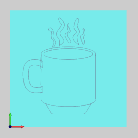
The first step in creating Emboss features is to define the stock area. The Emboss features are created within the defined stock area. The stock size can be modified at any time while creating Emboss features. If you try to add a feature before defining stock, the Create/Modify Stock dialog box is displayed first for you to define the stock as explained in the following steps.
1 In
the Data-CAM-Tree Manager, click
the ![]() BobART
Manager tab.
BobART
Manager tab.
2 In
the BobART tree, right-click ![]() Emboss Model
and click Create/Modify Stock.
Emboss Model
and click Create/Modify Stock.
3 The stock Origin is set to the default value of X0Y0Z0.
The origin is the lower-left corner of the stock, and the XYZ values are in reference to the WCS (world coordinate system) or CAD origin.
4 To set the stock size, in the Stock Parameters dialog box, type the following values.
Model Size
X = 8.000
Y = 8.000
5 To define the stock color, click Color.
In the Color dialog box, click the desired color, or define a custom color, and click OK.
6 In the Stock Parameters dialog box, click OK.
The stock is created and displayed in the Workspace.
1 In
the ![]() BobART
tree, right-click
BobART
tree, right-click ![]() Emboss Model, and click Emboss
Regular.
Emboss Model, and click Emboss
Regular.
2 In the Emboss dialog box, click in the Name box, and type Body at the beginning of the description so it displays Body Regular Emboss 1.
3 To define the color for this feature, click Color.
In the Color dialog box, click the desired color, and click OK.
4 In the Emboss group, click the Cross Section arrow, and click Convex Ellipse.
5 In the Major Axis box, type 0.1250.
6 In the Minor Axis box, type 0.2500.
The preview of the cross section is updated in the Emboss dialog box.
The cross section defines the shape of the emboss in Z.
7 In the Emboss group, set the Application Type to Add.
To confirm the selections and add the feature, click OK.
The parameters are now defined for the first emboss.
1 To hide the stock while selecting geometry, click anywhere in the Workspace and press (the shortcut key) E.
You can also right-click ![]() Emboss Model and click Blank/Unblank.
Emboss Model and click Blank/Unblank.
2 The
![]() Emboss feature
has been added to the BobART tree.
Emboss feature
has been added to the BobART tree.
If necessary, click ![]() to expand the
to expand the ![]() Body
Regular Emboss 1 - Add
feature in the tree.
Body
Regular Emboss 1 - Add
feature in the tree.
3 To
assign geometry, under ![]() Body Regular Emboss 1
- Add, right-click
Body Regular Emboss 1
- Add, right-click ![]() Geometry, and click Re/Select.
Geometry, and click Re/Select.
4 In the Edit menu, point to Select Entities, and click Pick By Layer.
In the Select Layer dialog box, click Body, and click OK.
The feature geometry is highlighted in the Workspace.
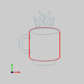
5 To
confirm the selection, right-click anywhere in the Workspace,
and click ![]() OK.
OK.
Every time that you make a change to an embossed model, the model must be regenerated to update the changes in the Workspace.
1 To show the stock, click anywhere in the Workspace, and press E.
You can also right-click ![]() Emboss Model and click Blank/Unblank.
Emboss Model and click Blank/Unblank.
2 In the BobART tree, right-click Emboss Model, and click Regenerate.
The model is updated in the Workspace.
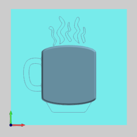
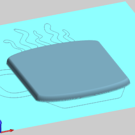
Notice in the previous images that the defined cross section is embossed from the selected feature geometry. The Application Type, Add, means that the emboss feature is added to the model (in the positive Z-axis direction of the WCS).
1 In
the ![]() BobART
tree, right-click
BobART
tree, right-click ![]() Emboss Model, and click Emboss
Regular.
Emboss Model, and click Emboss
Regular.
2 In the Emboss dialog box, click in the Name box, and type Bottom at the beginning of the description so it displays Bottom Regular Emboss 2.
3 To define the feature color, click Color.
Click the desired color, and click OK.
4 In the Emboss group, click the Cross Section arrow, and click Convex Ellipse.
5 In the Major Axis box, type 0.1250.
6 In the Minor Axis box, type 0.2500.
7 In the Emboss group, set the Application Type to Add.
To confirm the selections, click OK.
The feature is added to the BobART tree with the
label ![]() Bottom Regular
Emboss 2 - Add.
Bottom Regular
Emboss 2 - Add.
1 To hide the stock, click in the Workspace and press E.
2 To
assign geometry, under ![]() Bottom Regular Emboss 2 - Add,
right-click
Bottom Regular Emboss 2 - Add,
right-click ![]() Geometry,
and click Re/Select.
Geometry,
and click Re/Select.
3 In the Workspace, point to the lowest horizontal line as shown next.
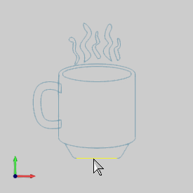
4 Press and hold Shift, and click the line.
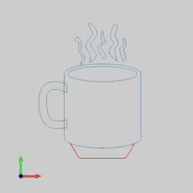
The continuous loop is selected as shown next.
(Notice that it does not appear that the entire loop is selected, even though it is. This is a result of overlapping entities in the Workspace obscuring the view. The way to verify your selection is explained in Step 6.)
5 To
confirm the selection, right-click anywhere in the Workspace,
and click ![]() OK.
OK.
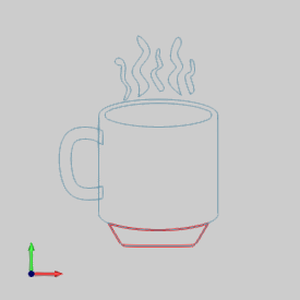
6 Notice that when you confirmed the geometry selection, the entire loop became highlighted. This is the feature geometry preview.
To show the preview of geometry that is already
assigned to a feature, click the name of the ![]() Emboss
feature in the BobART tree.
Emboss
feature in the BobART tree.
You can also click each ![]() Geometry
item, in the tree, to show the assigned geometry in the Workspace. For
example, click Body Regular Emboss 1
- Add.
Geometry
item, in the tree, to show the assigned geometry in the Workspace. For
example, click Body Regular Emboss 1
- Add.
The preview is displayed in the Workspace showing the feature geometry that was previously selected.

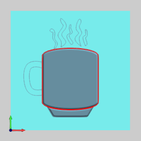
When working with BobART and creating geometry, there are various methods that you can use to help you stay organized. In this example, the geometry for each feature is assigned to a separate layer in the Layer-UCS-Post Manager. You can hide all layers, and then show only the geometry that is needed for each feature. This is one way to clarify what you are doing. The best method to use is whatever method you prefer, or whatever is the most efficient for a given scenario.
Every time that you make a change to an embossed model, the model must be regenerated to update the changes.
1 In the BobART tree, right-click Emboss Model, and click Regenerate.
The changes are added to the model.
2 To show the stock and view the changes, click anywhere in the Workspace, and press E.
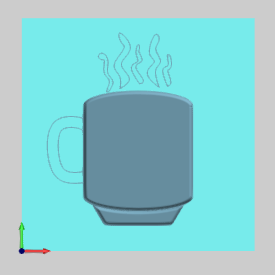
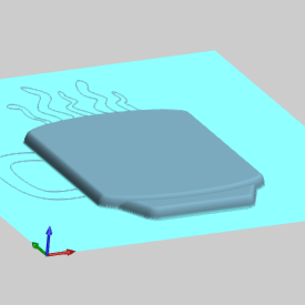
Notice that the second Emboss feature added material to the stock within the selected area. The appearance and height of the first two features are the same.
NOTE: The result of the two features created can also be accomplished using only one feature (because they use identical parameters). The geometry selection for a single Emboss Regular feature can contain multiple closed chains. (When multiple closed chains that overlap each other are used, the intersecting areas are not included in the emboss.)
1 In
the ![]() BobART
tree, right-click
BobART
tree, right-click ![]() Emboss Model, and click Emboss
Regular.
Emboss Model, and click Emboss
Regular.
2 In the Emboss dialog box, click in the Name box, and type Handle at the beginning of the description.
3 Select the color for the feature.
4 In the Emboss group, click the Cross Section arrow, and click Convex Ellipse.
5 In the Major Axis box, type 0.1250.
6 In the Minor Axis box, type 0.2500.
7 In the Emboss group, click the Application Type arrow, and click Merge High.
Click OK to add the feature.
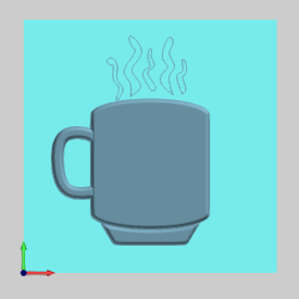
The Merge High Application Type keeps only the highest portion of the geometry, inside the intersecting areas, where multiple emboss features overlap. When the feature geometry does not overlap the geometry of another feature, it adds material to the stock in the same way as the Add Application Type. Because the Handle geometry overlaps the Body geometry and we want them to be at the same height in the model, the Merge High Application Type is used.
1 Before selecting geometry, hide the stock. (This step is not required. It is only done to make geometry selection easier.)
2 Under
![]() Handle Regular
Emboss 3 - Merge High, right-click
Handle Regular
Emboss 3 - Merge High, right-click ![]() Geometry,
and click Re/Select.
Geometry,
and click Re/Select.
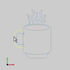
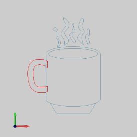
3 Press and hold Shift, and in the Workspace, click the handle geometry.
The entire chain is selected as shown in the second image.
4 To
confirm the selection, click ![]() OK.
OK.
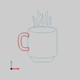
TIP: The Emboss Regular feature requires the feature geometry to be a closed shape. When creating geometry for Emboss features, the chain-selection method, shown in the previous steps, can be used to confirm that the geometry is continuous and closed. After creating geometry, enable selection mode and try to chain select (hold Shift and click) the loop. If the expected loop is selected, then the geometry should be good to use. If the entire loop is not selected, then there may be a gap in the geometry. Gaps can often be found by zooming-in to the point at which the loop selection stops. If there is a gap, repair the geometry, and then repeat the chain-selection test.
1 Show the stock.
2 In the BobART tree, right-click Emboss Model, and click Regenerate.
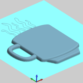
For this part of the tutorial, you edit the previous feature for two reasons. One is to show you how to modify an existing feature. The second is to show you the results of using the Add Application Type with overlapping features.
1 To
edit the feature, in the ![]() BobART tree, right-click
BobART tree, right-click ![]() Handle Regular Emboss
3 - Merge High, and click Edit.
Handle Regular Emboss
3 - Merge High, and click Edit.
2 In the Emboss dialog box, click the Application Type arrow, and click Add.
3 To confirm the changes, click OK.
4 To add the changes, Regenerate the model.
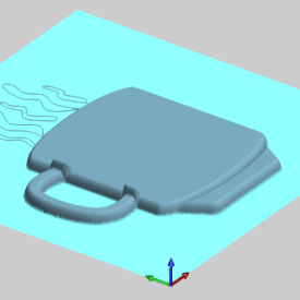
You can see that the overlapping area is twice the height of the rest of the model.
The parameters defined in each feature are added to each other.
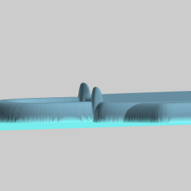
5 This is not the desired result for this example.
Edit
the feature, ![]() Handle
Regular Emboss 3 - Add, and
set the Application Type to Merge High.
Handle
Regular Emboss 3 - Add, and
set the Application Type to Merge High.
6 To accept the changes, click OK. (To update the model, Regenerate.)
1 In the BobART tree, right-click Emboss Model, and click Emboss Regular.
2 In the Emboss dialog box, click in the Name box, and type Top at the beginning of the description.
3 Select the color for the feature.
4 In the Emboss group, click the Cross Section arrow, and click Concave Arc.
5 In the Radius box, type 0.1250.
6 Set the Start Angle to 0.00, and set the End Angle to 90.00.
7 In the Emboss group, click the Application Type arrow and click Subtract. Click OK.
The Subtract Application Type removes material from the embossed model. This can be thought of as an emboss in the negative Z-axis direction.
1 Under
Top Emboss Regular 4 - Subtract,
right-click ![]() Geometry,
and click Re/Select.
Geometry,
and click Re/Select.
2 In Edit menu, point to Select Entities, and click Pick By Layer.
3 In the Select Layer dialog box, click Top Ellipse, and click OK.
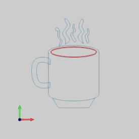
4 To confirm the selection, press the Spacebar.
1 In the BobART tree, right-click Emboss Model, and click Regenerate.
The result is subtracted from the model.
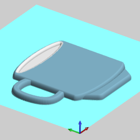
In the previous image, the color of the feature was changed to better show the subtracted feature.
1 In the BobART tree, right-click Emboss Model, and click Emboss Regular.
2 In the Emboss dialog box, click in the Name box, and type Steam at the beginning of the description.
3 Select a color for the feature.
4 In the Emboss group, click the Cross Section arrow, and click Convex Arc.
5 In the Radius box, type 0.3940.
6 Set the Start Angle to 0.00, and set the End Angle to 90.00.
7 In the Emboss group, click the Application Type arrow and click Merge High. Click OK.
1 Under
![]() Steam Regular Emboss
5 - Merge High, right-click
Steam Regular Emboss
5 - Merge High, right-click ![]() Geometry, and click Re/Select.
Geometry, and click Re/Select.
2 In the Workspace, point to the top-left side of the steam geometry.
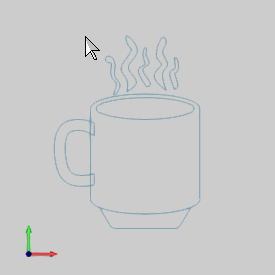
3 Click and drag (hold the mouse button down) a window around the steam geometry as shown next.
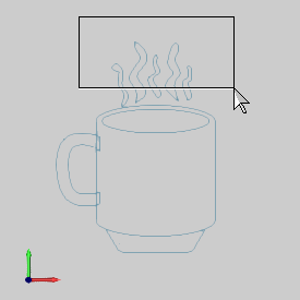
4 To
confirm the selection, click ![]() OK.
OK.
TIP: If
for any reason unwanted geometry is selected, you can click each unwanted
entity to remove it from the selection. Sometimes this method may not
be the most efficient, for example, when there are many small entities
that need to be removed. To completely
start over with geometry selection, click ![]() Cancel. You can also press Esc.
After cancelling the selection, to start over, right-click Geometry and click Re/Select.
Cancel. You can also press Esc.
After cancelling the selection, to start over, right-click Geometry and click Re/Select.
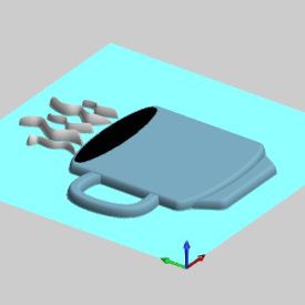
1 Right-click Emboss Model, and click Regenerate.
1 In the File menu, click Save As.
2 In the Save As dialog box, navigate to the location in which you want to save the file.
3 In the File Name box, change the name to My Coffee Mug.
4 To save the file with the new name, click Save.
Congratulations! You have just created an Embossed Model using only the Emboss Regular feature.
The coffee mug that you created in this tutorial is continued in How to Create an Emboss Swept.
This concludes the tutorial.