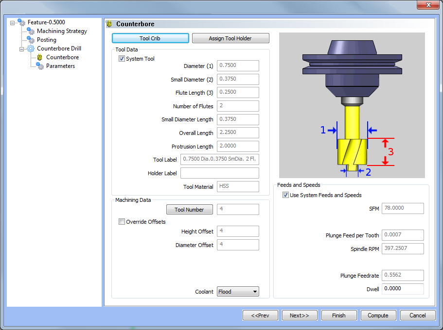
Counterbore Drill Operation Tool Page
Introduction
The Mill Hole Counterbore Drill operation has only one tool type to choose from. It is good practice to have all the tools for the job loaded into the Tool Crib at the start of the job. By this point, those tools should already be in the Tool Crib, and the system will have pulled appropriate tools for each operation from the Tool Crib. From this tool page, you can either, choose a different tool from the Tool Crib, go into the Tool Crib to add tools from your Tool Library, or enter tool specific data manually into the Tool Data Section of the page.
This page will also assist in assigning Tool Numbers and Offsets, Spindle Direction and Coolant options, as well as Speeds and Feeds.
Tool Crib - opens the Tool Crib for you to select a tool that you have already loaded for the job. Click to select a tool in the tools list, and click OK to assign the tool to the operation. (For Mill Turn jobs, view Mill Turn Tool Crib.)
Assign Tool Holder (Mill and Lathe Drilling) - opens the Milling Tool Holder Library to assign a tool holder to the tool. In the Tool Holder list on the right, select a tool holder/arbor, then click OK. The name of the selected tool holder appears in the Holder Label box. This holder is now the default tool holder for the tool, meaning that it is automatically assigned to the tool when you create an operation with this tool.
Tool Data
To select a tool for the feature, you can use the following option in one of two ways.
-
System Tool
 Select this check
box to allow the software to automatically select tools from the Tool
Crib that match the machining
operation. In the case of end mills, you may alter the diameter and corner
radius allowing the software to find the appropriate tool from the Tool
Crib. In the case the appropriate tool sizes are not found, the software
searches for a matching tool in the Tool Library. If a matching tool is
found, it is added to the Tool Crib. If a matching tool is not found,
a new tool is automatically created and added to the Tool Crib.
Select this check
box to allow the software to automatically select tools from the Tool
Crib that match the machining
operation. In the case of end mills, you may alter the diameter and corner
radius allowing the software to find the appropriate tool from the Tool
Crib. In the case the appropriate tool sizes are not found, the software
searches for a matching tool in the Tool Library. If a matching tool is
found, it is added to the Tool Crib. If a matching tool is not found,
a new tool is automatically created and added to the Tool Crib.
![]() When this check
box is cleared, you can edit all tool information directly in the dialog
box. In this case, the defined tool is added to the Tool Crib.
When this check
box is cleared, you can edit all tool information directly in the dialog
box. In this case, the defined tool is added to the Tool Crib.
The following items are displayed for informational purposes:
|
|
Note: Tools and tool holders may be added or modified in the Tool Crib when it is accessed from the Milling Wizard Tool dialog box.
Machining Data
The Machining Data parameters change slightly depending on whether you are in a Turning job or Mill Turn job. All parameters are explained next.
-
Tool Number - opens the Assigned Tools dialog box for you to change the tool numbering.
-
Override Offsets
![]() Clear the Override Offsets check box to use the tool number to set the
Offset Register value.
Clear the Override Offsets check box to use the tool number to set the
Offset Register value.
Select the Override Offsets check box to allow for manual editing of the
Offset Register value.
-
Offset Register - sets the register on the machine that stores the height and diameter offset values for the tool.
-
Coolant - sets the coolant option for the operation. Select one of the following options: Off, Flood, Mist, Air, or Oil.
Feeds and Speeds
By default, the software automatically calculates feeds and speeds based on the values defined in the Stock Material Library.
-
Use System Feeds and Speeds
Select this check
box to automatically calculate the feeds and speeds.
![]() Clear this check
box to type feeds and speeds values in the dialog box.
Clear this check
box to type feeds and speeds values in the dialog box.
- SFM/SMM - is the surface feet/meters per minute feedrate.
- Plunge Feed per Tooth - is the feedrate for plunge moves in units per tooth.
- Spindle RPM - is the revolutions per minute of the spindle.
- Plunge Feedrate - is the feedrate for plunge moves.
-
Dwell - sets the amount of seconds to Dwell.
Tip: While editing the feeds and speeds, changing one value automatically calculates any other associated values. For example, if you modify the SFM value, the Spindle RPM, Cutting Feedrate, and Plunge Feedrate are automatically calculated.
Next Topic
Once the Rough Tool variables have been set, click Next>> to continue to the Parameters page.