The Nesting Overview
Introduction
The Nesting module is a complete nesting solution for nesting parts and creating toolpath for optimized material utilization. This topic serves as an overview of creating nesting programs and also serves as a navigation tool to all nesting topics in this help system.
Getting Started with Nesting
The first part of creating a nesting program is to create the geometry of the parts to be nested. Wherever the parts to be nested are situated in the CAD window, they will not interfere with the nested result, besides posing a possible visual nuisance. Due to this possibility, it is recommended that you draw, or move, the geometry outside of the quadrant in which you intend to place the nesting stock. You can also load geometry from external files, such as .bbcd, .dxf, .dwg or .cad. The nesting sheet, or stock, defines the sheet of material from which the nested parts are cut. Be sure to go into the Nesting Wizard knowing how the stock will be placed on the machine in reference to machine zero. Since the WCS will be the machining origin, you need to define the values in the Sheets Parameters page of the Nesting Wizard so that the corner of the sheet will be referenced to the WCS as the actual stock corner will be referenced to the machine zero.
Important: If you are nesting parts that contain drilling operations, which are already open in your CAD window, you must create a layer named Holes in the Layer-UCS-Post Manager. The geometry of the holes, and not the entire nested part, must be placed on this layer. In addition, if the nested parts contain any Dado, or open geometry that should be cut, this geometry must be placed on a layer named Dado. When importing parts, each type of geometry being on its own layer is the only imperative. For more information, view the links listed at the end of this topic.
After creating the geometry of all the parts being nested, you are ready to create a Nesting Job.
Navigation
To create a Nesting Job, do one of the following:
- In the CAM
Tree, right-click
 CAM Defaults, and click New Job.
- In the CAM Job group, of the CAM ribbon, click
 New CAM Job.
The Machining Job dialog box displays.
Select Nesting, select a Machine, and click Nesting Wizard to begin the job.
The Nesting Wizard
You can navigate through the Nesting Wizard either by clicking the Next>> or <<Prev buttons to move sequentially through the wizard or by clicking on the name of the page you wish to visit in the tree on the left of the wizard. The Nesting Wizard contains up to eight types of pages: Part Geometry, Parts Parameters, Tabs, Sheet Parameters, Nesting Parameters, and three Default Features. The Default features listed will vary depending on the operations being completed with the wizard. Default Profiles, Default Hole and Default Dado can all be listed. Click the links at the end of the Nesting Wizard to learn more.
The Nesting Job
The Nesting Job in the CAM Tree provides the tools needed to define job settings, machine and post processor selection, tools, sheets, and feature operations. Click here to view more about what is included in the Nesting Job in the CAM Tree.
Nesting Example
An example nesting result is shown next.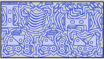
Next Topic
Understanding Basic Part Geometry