No Compensation
Introduction
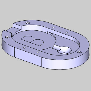
This example will demonstrate using no compensation in CAM operations, and will provide links to related topics.
No Compensation Example
For each operation you can choose to use compensation or not. When using compensation, you can choose to use System Compensation, Machine Compensation, or a combination of both. This example will explore system compensation and the direction of the selected chain.
Important: When using no compensation, the tool will not be offset from the path.
Create a Mill 2 Axis Feature
- In the CAM Tree, right-click the Machine Setup - 1 and select Mill 2 Axis.
The Mill 2 Axis Wizard appears.
Feature Geometry Picking
- Click Select Geometry.
The Feature Geometry Picking dialog appears. Focus is automatically placed on the Selected Geometry list allowing you to choose the feature geometry from the graphics area.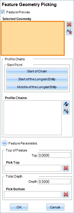
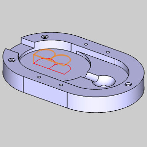
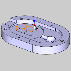
- In the Layer Manager, we turn off the layer containing the part so we can easily select the geometry to engrave.
- In the graphics area, window pick the remaining geometry.
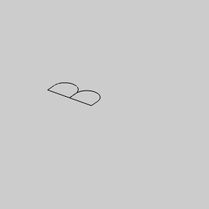
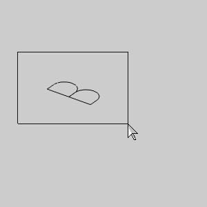
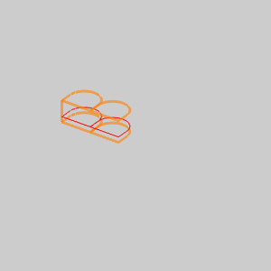
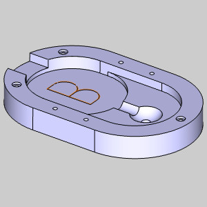
The geometry is added to the Selected Geometry list, and the feature preview is visible.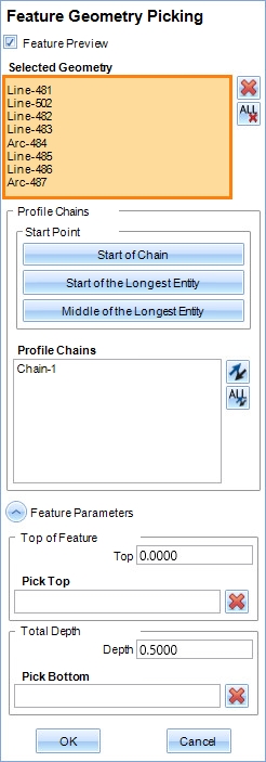
- At the bottom of the Feature Geometry Picking dialog, click in the Pick Top list.
The list is given focus.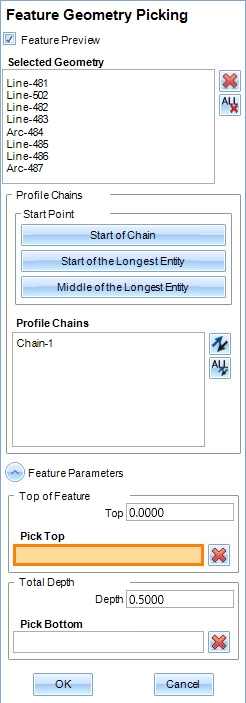
- In the graphics area, click a snap point level with the surface to be engraved.
The snap point is added to the Pick Bottom list, and the Depth is updated.
- In the Total Depth group, update the Depth to 0.0500.
- Click OK.
The Mill 2 Axis Wizard reappears.
Setting the Machining Strategy
- In the tree in the left of the wizard, click Machining Strategy.
- In the Current Operations list, highlight Profile Rough and click the Delete button.
- Click Next>> to update the Wizard.
Setting the Tool
- In the tree in the left of the wizard, click Finish to move to the tool page.
- Update the Diameter to 0.1250, and the Corner Radius to 0.0625.
Setting the Compensation
- In the tree in the left of the wizard, click Pattern.
- In the Compensation group, change System Compensation to Off.
Setting the Leads
- In the tree in the left of the wizard, click Leads.
- In the Entry group, select Ramp.
- Set the Angle of Approach to 0.25000.
- Click Compute.
The toolpath is created. Pressing S will allow you to turn off Shaded view.
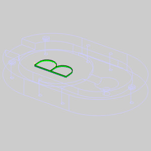
By zooming in you will notice the ramp we used to complete our engrave.
Related Topic
Example: System Compensation Only
Example: Machine Compensation Only