System and Machine Compensation
Introduction
This example will demonstrate using system and machine compensation in CAM operations at the same time, and will provide links to related topics.
System and Machine Compensation Example
For each operation you can choose to use compensation or not. When using compensation, you can choose to use System Compensation, Machine Compensation, or a combination of both. This example will explore the combination of system and machine compensation and the direction of the selected chain.
Important: When using a combination of system and machine compensation, BobCAD has already handled offsetting the path in the amount of the tool radius used in the operation. This means the value entered for the tool in the controller can be set to zero unless fine adjustments are needed.
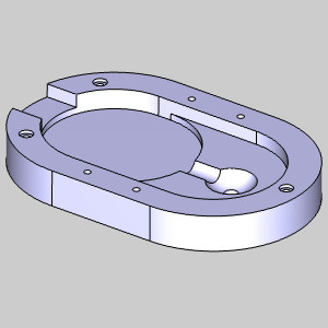
Create a Mill 2 Axis Feature
- In the CAM Tree, right-click the Machine Setup - 1 and select Mill 2 Axis.
The Mill 2 Axis Wizard appears.
Feature Geometry Picking
- Click Select Geometry.
The Feature Geometry Picking dialog appears. Focus is automatically placed on the Selected Geometry list allowing you to choose the feature geometry from the graphics area.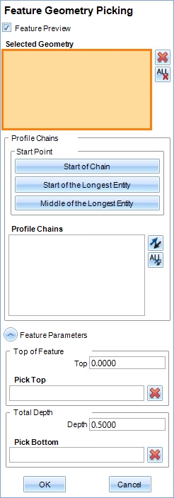
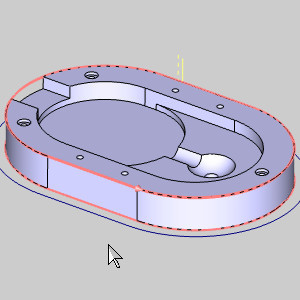
- In the graphics area, right-click the edge of the part and select Constant Z.
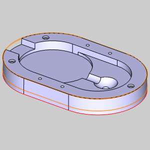
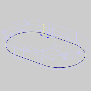
The geometry is added to the Selected Geometry list, and the feature preview is visible.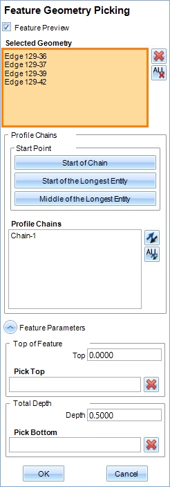
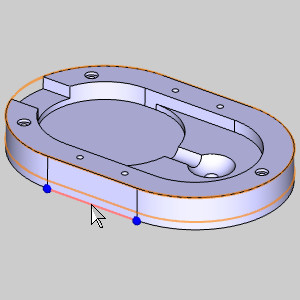
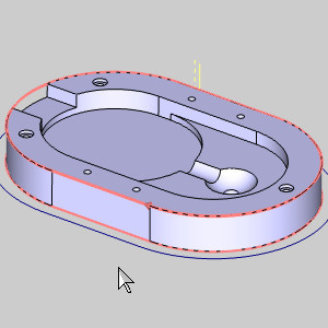
- In the Profile Chains list of the Feature Geometry Picking dialog, click Chain-1.
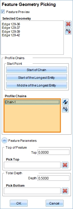
The chain direction is displayed in the graphics area. Pressing S will allow you to turn off Shaded view.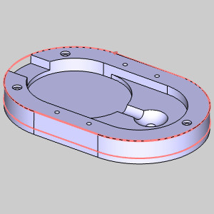
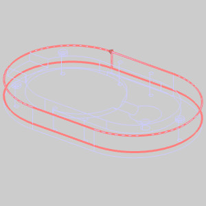
We will leave our chain in its counter clockwise direction for now. - At the bottom of the Feature Geometry Picking dialog, click in the Pick Bottom list.
The list is given focus.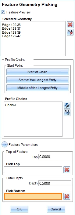
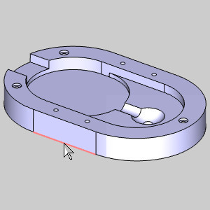
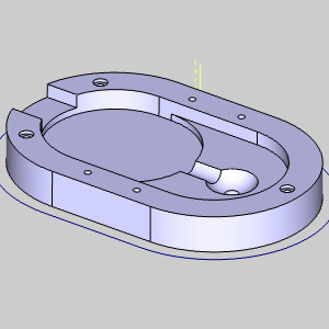
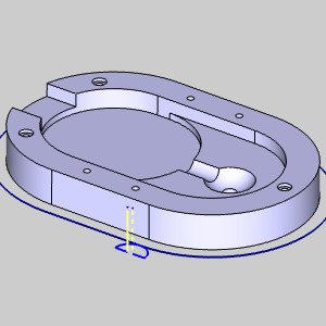
- In the graphics area, click the bottom edge of the model.
The snap point is added to the Pick Bottom list, and the Depth is updated.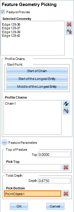
Note: Clicking the actual snap point that appears is not necessary. When you select an edge to pick a point, the closest snap point is always used.
- Click OK.
The Mill 2 Axis Wizard reappears.
Setting the Strategy and Leads
- In the tree in the left of the wizard, click Machining Strategy.
- In the Current Operations list, highlight Profile Rough and click the Delete button.
- In the tree in the left of the wizard, click Leads.
- In the Lead-in group, select Circular.
- In the Arc group, set the Radius to 0.3000.
- Click Compute.
The toolpath is created.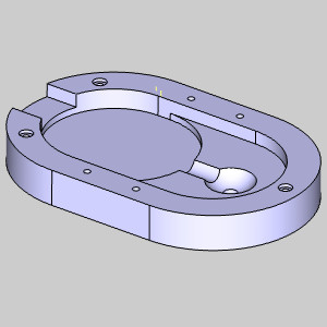
Warning: When using machine compensation, be sure to use a lead-in and a lead-out. Machine compensation is only called during a linear lead-in motion, and canceled during a linear lead-out. Because of this, it is also important to make sure the lead is large enough to accommodate the tool radius having no additional compensation at the start, and only fully compensated at the end of the first linear lead move. Since we are using a combination of System and Machine Compensation, this is less of a worry since BobCAD is already handling the majority of the compensation. For more information about this, see the No Compensation example.
Updating Compensation
By default, Left System Compensation is used. With the default counter clockwise direction, this puts us on the wrong side of the selected geometry.
- In the CAM Tree, right-click Feature 2 Axis and select Edit.
The Mill 2 Axis Wizard returns. - In the tree on the left side of the wizard, click Patterns to open the Patterns page.
- In the Compensation group, change System Compensation to Right.
- In the Compensation group, change Machine Compensation to Comp Right / G42.
- Click Compute.
The toolpath is updated. With the counter clockwise direction of our chain, we are now using a conventional cut.
We will change this to a climb cut.
Updating Chain direction
- In the CAM Tree, right-click the Geometry item in our Feature 2 Axis, and select Re/Select.
The Feature Geometry Picking dialog opens. - In the Profile Chains list, click Chain-1.
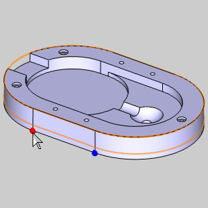
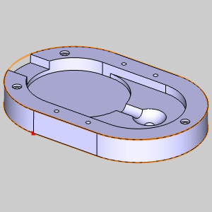
The chain is displayed in the graphics area. - Click the closer side of the part.
The chain start point moves to the closes snap point.
Our direction is still counter clockwise. - Click the same area.
The chain reverses direction. Computing the feature now, would place the toolpath inside the part again. To avoid this, we will change our compensation again.
Updating Compensation
- In the CAM Tree, right-click Feature 2 Axis and select Edit.
The Mill 2 Axis Wizard returns. - In the tree on the left side of the wizard, click Patterns to open the Patterns page.
- In the Compensation group, change System Compensation back to Left.
- In the Compensation group, change Machine Compensation to Comp Left / G41.
- Click Compute.
The toolpath is updated. With the clockwise direction of our chain, we are now using a climb cut.
Related Topic
Example: System Compensation Only