Barrel Mill Tool Overview
Introduction
This topic will explain a little about Barrel Mills, describe how to access them, will list the operations they can be used for, and will explain the definition of the Advanced type in detail.
Barrel Mills
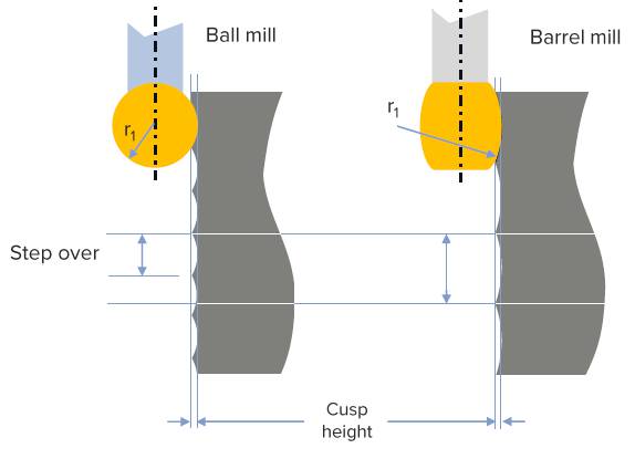
Barrel Mills are designed to be able to take a larger depth of cut, while maintaining the desired cusp height.
There are seven basic types of available Barrel Mills available:
|
Supported Barrel Mill Tool Types:
|
||||
|
Standard
|
Advanced
|
|||
|
||||
|
Double
|
Section
|
|||
Navigation
To create or edit Barrel Mill tools you will need to access the Tool Library. This can be accomplished in one of the following ways:
- In the CAM Tree, right-click CAM Defaults and select Tool Library.
The Tool Library dialog launches. - In the CAM Tree, right-click Milling Tools and select Tools.
The Tool Library dialog launches, but is filtered to show only Milling Tools. - In the Tool page of the Wizards, click Tool Crib. With the Tool Crib open, highlight the desired Barrel Tool type and select Add From Tool Library.
The Tool Library dialog launches, but is filtered to show only the highlighted Barrel Tool type.
Operations
The chart below will show all available Barrel Mill types, and the operations they are available for.
| Supported Barrel Mill Tool Types | |||||||
|---|---|---|---|---|---|---|---|
|
Standard
|
Advanced
|
Tangent
|
Lens
|
Taper
|
Double
|
Section
|
|
| Advanced Rough |
|
|
|
|
|
|
|
| Flatlands |
|
|
|
|
|
|
|
| Pencil |
|
|
|
|
|
|
|
| Advanced Planar |
|
|
|
|
|
|
|
| Project Curves |
|
|
|
|
|
|
|
| Advanced Z Level Finish |
|
|
|
|
|
|
|
| 4 Axis Rotary |
|
|
|
|
|
|
|
| Parallel cuts |
|
|
|
|
|
|
|
| Cuts along curve |
|
|
|
|
|
|
|
| Morph between 2 curves |
|
|
|
|
|
|
|
| Parallel to multiple curves |
|
|
|
|
|
|
|
| Project Curves |
|
|
|
|
|
|
|
| Morph between 2 surfaces |
|
|
|
|
|
|
|
| Parallel to surface |
|
|
|
|
|
|
|
| Flowline |
|
|
|
|
|
|
|


The Advanced Barrel Mill Tool
While many barrel mill tools are fairly easy to define, such as the Tangent or Taper styles, some of the barrel mill style tools can go a little outside the scope of the standard definitions. In cases like these, use the Advanced Barrel Mill. The Advanced Barrel Mill is the only one of the barrel mill types that allows you options on particular features when defining the profile of the tool.
When defining the tool, the definitions that offer choices are:
- Flute Height by:
- Upper Diameter
- Length
- Profile Position by (Axial):
- Distance(M)
- Reference Diameter
- Profile Position by (Radial):
- Distance(M)
- Max Diameter
- Corner Radius Type:
- None
- Corner
- Full
Flute Height by
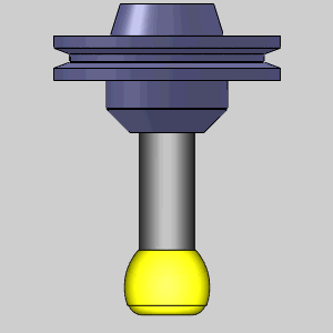
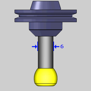
The Flute Height by parameter gives you the option to define the height of the flutes by either the upper diameter, or the flute length. In the table below, you will see each choice, the parameter it presents, and an image of that parameter.
| Upper Diameter | Length |
| Shaft Diameter (6) | Flute Length (2) |
|
|
Profile Position by (Axial)
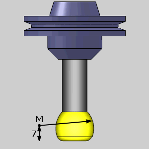
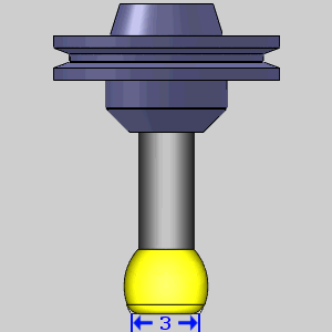
The most prominent aspect of the tool is its main radius (M), and the position of that radius. This is referred to as the Profile Position, and requires two parameters to define it properly. The first is the Axial definition. The axial definition can be defined with either Distance(M), which is the height of the arc center from the tool tip, or with the Reference Diameter, which is what the diameter at the tool tip would be if there were no corner radius. In the table below, you will see each choice, the parameter it presents, and an image of that parameter.
| Distance(M) | Reference Diameter |
| Distance(M) (7) | Diameter (3) |
|
|
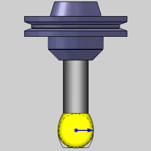
Profile Position by (Radial)
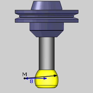
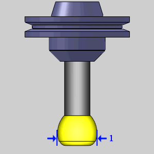
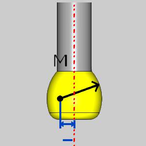
The second definition needed to describe the main radius of the tool (M), and its position, is the Profile Position by (Radial). This can be defined by either the Distance(M), or the Max Diameter. The Distance(M) describes the distance from the center of the main radius to the center of the tool. The Max Diameter describes the full diameter of the tool itself, and not necessarily the radius (M) of the profile. In the table below, you will see each choice, the parameter it presents, and an image of that parameter.
| Distance(M) | Max Diameter |
| Distance (M) (8) | Diameter (1) |
|
|
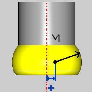
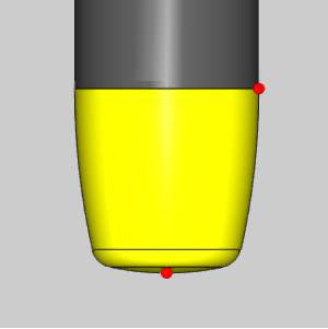
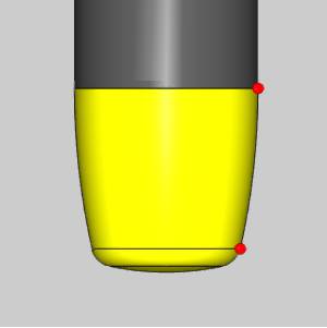
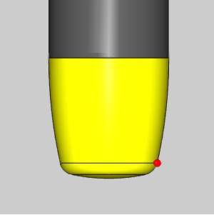
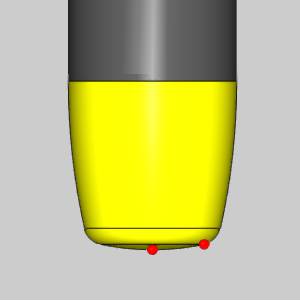
Important: Distance(M) (8): This value will typically be negative, unless the arc and its center are on the same side of the revolved axis as seen in the images below.
| Distance(M) | Distance(M) |
| Negative Value | Positive Value |
|
|
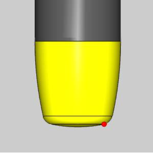
Corner Radius Type
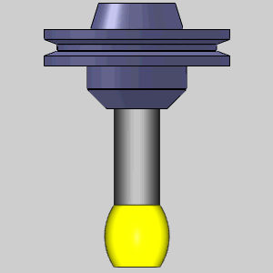
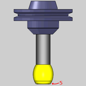
There are three options when it comes to the corner radius of the tool. You can choose between either None, Corner, or Full. When None is chosen there is no parameter added and no corner radius is added. When Corner is chosen the Corner Radius (5) is added to allow you to enter the specify radius to use. When Full is chosen there is no parameter added, no additional parameter is added, but the tool will utilize the widest point of the radius from the center of the tool to round the bottom as shown in the image below. In the table below, you will see each choice, the parameter it presents, and an image of that parameter.
| None | Corner | Full |
| (No additional value is added to the definition) | Corner Radius (5) | (No additional value is added to the definition) |
|
|
|
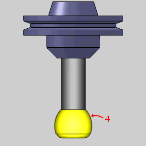
Profile Radius (4)
Regardless of the options you use to define the tool shape, each and every tool will allow you to enter the Profile Radius (4). This is the main radius of the tool.
| Profile Radius (4) |
|
Cutting Tips
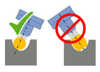
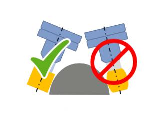
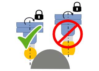
Where not to use Barrel Tools
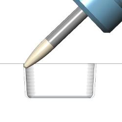
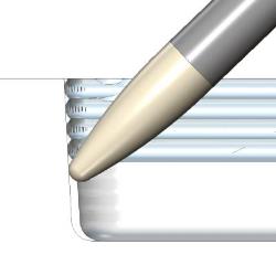
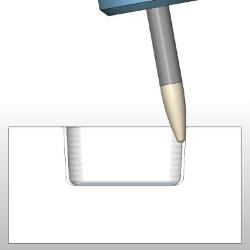
While barrel tools are a huge help in many circumstances, their strength can also be their weakness:
| Concave radii smaller than the barrel radius | Convex shape orthogonal to feed direction | If you are unable to perform the described tilting |
|
|
|
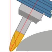
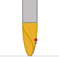
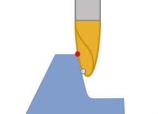
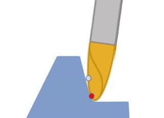
Using the Contact Point
In the Tool axis control page, you can set Tool axis will ... to Be tilted relative to cutting direction. You will then have the option to Set side tilt by. This tilt of the tool can then be defined by either:
| Angle | Contact point |
|
|
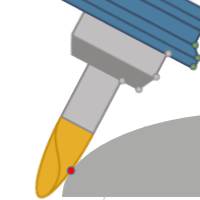
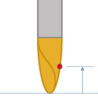
Choosing the Contact point option then allows you to specify how that contact point is defined with the Contact point definition parameter. You can place this contact point on the tool by defining either:
| By height | By line parameter |
|
|
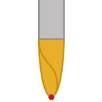
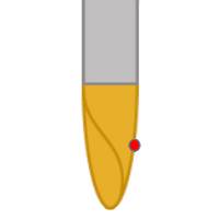
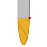
The values used for the contact point are between 0 and 1 which represent 0% to 100% of the flute height, or along the profile line.
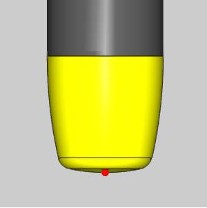
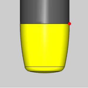
| 0.0 | 0.5 | 1.0 |
|
|
|
When using the By line parameter option, you can also define the Considered profile section by either:
- Full Profile
- Barrel section
- Convex tip section
Note: While the Full profile is active for all tools, the Barrel section is available only for Barrel Mill tool types. The Convex tip section option is only available for the Double Profile, and Lens barrel types.
| Full Profile | 0.0 | 1.0 |
|
|
|
| Barrel section | 0.0 | 1.0 |
|
|
|
| Convex tip section | 0.0 | 1.0 |
|
|
|
By utilizing the contact point, and setting a To value, you can force the tool to begin the toolpath at one contact point, and end at another:
| Start Value | End Value |
|
|
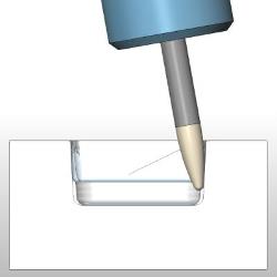
Example
This example will demonstrate a generic job being finished with a Tangent barrel tool. This short example will display images of the toolpath as it would appear if you were to Compute at that time although it does not instruct you to calculate until the end.
Tip: In general it is good practice to use a much looser tolerance than required so you can calculate after every value or parameter you update. This way you will not have to wait long to see the result, and you will be able to see what the result is from the single change made instead of wondering which of the changes you made contributed to which aspect of the updated toolpath.
This example will also display images showing the what the current state would look like in simulation although it never instructs you to simulate the part. This example is designed to help illustrate:
- Setting Drive surfaces and Maximum stepover
- Gouge checking
- Setting Tool axis control
- Adjusting Linking
Setting the Drive surfaces and Maximum stepover
- With the part open, we create a Multiaxis feature in our CAM Tree.
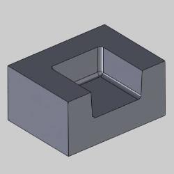
- For this example the Parallel cuts toolpath is used with a Tangent barrel tool.
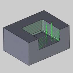
In the Pattern group of the Surface paths page, the drive surfaces are selected, and the Constant Z option is selected.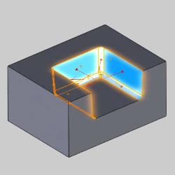
- While still in the surface paths page, we enter a 0.125 inch Maximum stepover in the Stepover group.
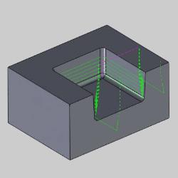
Gouge checking
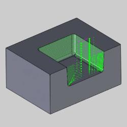
- In this case, we skip over the Tool axis control page to set a Gouge check.
In the Gouge check page, select the first Status and the check boxes for all Check options.
In the Strategy and parameters group, use Trim and relink toolpath with the Trim collision only option, and pick the surfaces to check in the Geometry group.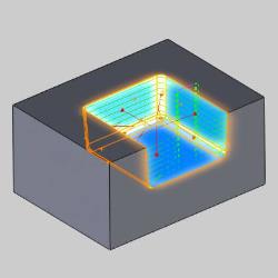
This removes most of the path, since our tool axis is still at default:
Setting Tool axis control
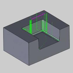
- On the Tool axis control page, the default for the Tool axis will ... parameter is Be tilted relative to cutting direction.
Under this parameter, set the Set side tilt by parameter to Contact point. - We use the default for the Contact point definition parameter: By height.
We adjust the Height in percent of flute length value to achieve the proper contact point.
Setting this value to 0.02 will not produce sufficient tilt: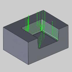
In this case, we will use a value of 0.2, or 20% the height of the flute: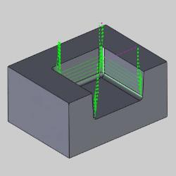
Adjusting Linking
- In the Link page, we first set leads for the Entry/Exit group.
Assign the First entry, and Last exit to Use Lead-In, and Use Lead-Out respectively. We set each of these leads to Tangential line:
The lifts in the corners are from our gouge checking trimming collisions. Currently our Gaps along cut is set to Retract to clearance area for Large gaps. - In the Gaps along cut group, set the Large moves parameter to Follow surfaces, and leave the Don't use Lead-In/Out option as it is.
- In the Links between slice group, set the Large moves parameter to Blend spline, and leave the Don't use Lead-In/Out option as it is.
Click Compute.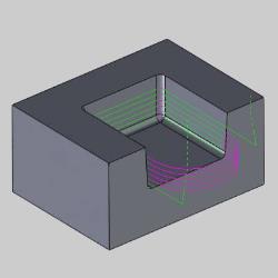
This gives us a smooth flow from one cut to the next.
Related Topics
For more information on the parameters of the barrel tools, see the Tool Library topic.