Tool Library
- Tool Library
- Introduction
- The Tool Library
- Navigation
- The Dialog Box Parameters
- Drill
- Mill
- Endmill Rough
- Endmill Finish
- Chamfer Mill
- Corner-Round
- Thread Mill
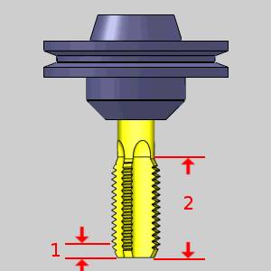
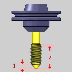
- Single Point Thread
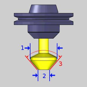
- V-Tool
- Tapered
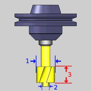
- T-Cutter
- Dove Mill
- Lollipop
- Drag Knife
- Barrel-Standard
- Barrel-Advanced
- Barrel-Tangent
- Barrel-Lens
- Barrel-Taper
- Barrel-Double
- Barrel-Section
- Turning
- Related Topics
- Next Topic
Introduction
This topic will explain the Tool Library, explain where the tool library can be accessed from, explain the options found in it, and provide links to related topics.
The Tool Library
The Tool Library contains all of the available system tools based on the main categories Drill, Mill, Lathe, Laser, Plasma, and Waterjet. This dialog box is used to add, delete, and modify tools. You can also load tool information from a previously saved file. On the left side of the dialog box is a list of the supported tool types. The right side contains the tool parameters list for each tool.
Tip: To learn about all the functionality available in the Tool Library, see the Tool Library Functionality topic.
Taking the time to create all of the tools in your shop can greatly speed up the process of creating milling features. You can then add the tools to the Tool Crib to quickly create the equivalent of the tool changer for each job. The Tool Crib tool list can be saved to a file for repeated use.
When you select a tool for a feature wizard operation, a filtered version the Tool Library is displayed which only displays the appropriate tool types based on the operation type.
Navigation
To access the Tool Library, do one of the following:
- In the CAM
Tree, right-click
 CAM Defaults,
and click Tool Library.
CAM Defaults,
and click Tool Library.
This method is used to view, add, or modify tools in the Tool Library.
-
In the CAM
Tree, right-click
 Milling Tools,
  Turning Tools,
or Mill Turn Toolsand click Tool Library.
Turning Tools,
or Mill Turn Toolsand click Tool Library.
Note: This opens the Tool Library showing only tools for the selected job type (Mill, Lathe, or both in the case of a Mill Turn job).
- In the Tool Crib dialog box, click Add From Tool Library.
Note: This method is used to add a tool from the Tool Library to the Tool Crib, and accesses a filtered version of the Tool Library which shows only the tool type being added.
The Dialog Box Parameters
From this tool page, you can either, choose a different tool from the Tool Crib, go into the Tool Crib to add tools from your Tool Library, or enter tool specific data manually into the Tool Data Section of the page. This page will also assist in assigning Tool Numbers and Offsets, and Coolant options, as well as Speeds and Feeds.
-
 Save As - opens the Save As dialog to allow you to save the library as either a .MTOOLS file, or a .XML file of a particular name. This can then be imported on another work station and merged into that library.
 -
 Import
from File - displays the Open dialog box allowing you to navigate
to and load a previously saved Tool Library, or MachiningCloud file (.mtools, .ltools, .xml or .zip). This option will merge the selected tool library file into your existing library. In the case of using the MachiningCloud .zip, selecting and opening the file will launch the MachiningCloud Import dialog.
Import
from File - displays the Open dialog box allowing you to navigate
to and load a previously saved Tool Library, or MachiningCloud file (.mtools, .ltools, .xml or .zip). This option will merge the selected tool library file into your existing library. In the case of using the MachiningCloud .zip, selecting and opening the file will launch the MachiningCloud Import dialog. -
 Add
- automatically creates a default tool and places it in the Tool Parameters section to allow you to modify it.
Add
- automatically creates a default tool and places it in the Tool Parameters section to allow you to modify it.
-
 Delete
- removes the selected tool.
Delete
- removes the selected tool.
- OK - confirms the changes made to the tools and closes the Tool Library dialog.
- Cancel - closes the Tool Library dialog without saving any changes made to the library.
Note: The available Tool Parameters vary depending on the type of tool selected. Click on a tool to display the Tool Parameters for that particular tool.
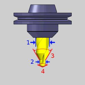
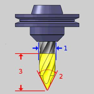
Drill
 Center Drill
 Tool Parameters
|
|
Tool Holder
- Holder
Label - displays the name of the associated tool holder.
When blank, no tool holder is associated.
- Assign/Remove Tool Holder - When no tool holder has been assigned, the Holder Label will be blank, and the button will read: Assign Tool Holder. This will open The Milling Tool Holder Library to allow you to select, or create a tool holder to associate with the selected tool. Once a tool holder has been assigned, the button will read: Remove Tool Holder. This will remove the association between the tool holder and the selected tool.
Feeds and Speeds
- Use System
Feeds and Speeds
 Select this check
box to automatically calculate the feeds and speeds.
Select this check
box to automatically calculate the feeds and speeds. Clear this check
box to type feeds and speeds values manually.
Clear this check
box to type feeds and speeds values manually. - Spindle Speed/RPM - is the revolutions
per minute of the spindle.
- Plunge Feedrate - is the downward feedrate. This value is linked to the Plunge Feed per Tooth.
Custom Geometry
- Assign Tool Geometry - hides the Tool Library and opens the Tool Shape Picking dialog to allow you to select geometry from the graphics area to assign as the shape of the tool. You can learn more about assigning custom tools in the Assigning Custom Tools topic.
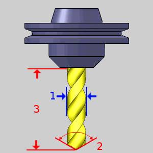
Drill
Tool Parameters
|
|
Tool Holder
- Holder
Label - displays the name of the associated tool holder.
When blank, no tool holder is associated.
- Assign/Remove Tool Holder - When no tool holder has been assigned, the Holder Label will be blank, and the button will read: Assign Tool Holder. This will open The Milling Tool Holder Library to allow you to select, or create a tool holder to associate with the selected tool. Once a tool holder has been assigned, the button will read: Remove Tool Holder. This will remove the association between the tool holder and the selected tool.
Feeds and Speeds
- Use System
Feeds and Speeds
Select this check
box to automatically calculate the feeds and speeds. Clear this check
box to type feeds and speeds values manually. - Spindle Speed/RPM - is the revolutions
per minute of the spindle.
- Plunge Feedrate - is the downward feedrate. This value is linked to the Plunge Feed per Tooth.
Custom Geometry
- Assign Tool Geometry - hides the Tool Library and opens the Tool Shape Picking dialog to allow you to select geometry from the graphics area to assign as the shape of the tool. You can learn more about assigning custom tools in the Assigning Custom Tools topic.
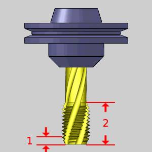
Spiral Tap
Tool Parameters
|
|
Tool Holder
- Holder
Label - displays the name of the associated tool holder.
When blank, no tool holder is associated.
- Assign/Remove Tool Holder - When no tool holder has been assigned, the Holder Label will be blank, and the button will read: Assign Tool Holder. This will open The Milling Tool Holder Library to allow you to select, or create a tool holder to associate with the selected tool. Once a tool holder has been assigned, the button will read: Remove Tool Holder. This will remove the association between the tool holder and the selected tool.
Feeds and Speeds
- Use System
Feeds and Speeds
Select this check
box to automatically calculate the feeds and speeds. Clear this check
box to type feeds and speeds values manually. - Spindle Speed/RPM - is the revolutions
per minute of the spindle.
Custom Geometry
- Assign Tool Geometry - hides the Tool Library and opens the Tool Shape Picking dialog to allow you to select geometry from the graphics area to assign as the shape of the tool. You can learn more about assigning custom tools in the Assigning Custom Tools topic.
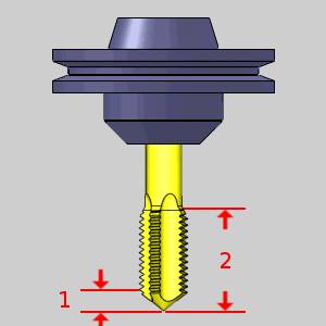
Point Tap
Tool Parameters
|
|
Tool Holder
- Holder
Label - displays the name of the associated tool holder.
When blank, no tool holder is associated.
- Assign/Remove Tool Holder - When no tool holder has been assigned, the Holder Label will be blank, and the button will read: Assign Tool Holder. This will open The Milling Tool Holder Library to allow you to select, or create a tool holder to associate with the selected tool. Once a tool holder has been assigned, the button will read: Remove Tool Holder. This will remove the association between the tool holder and the selected tool.
Feeds and Speeds
- Use System
Feeds and Speeds
Select this check
box to automatically calculate the feeds and speeds. Clear this check
box to type feeds and speeds values manually. - Spindle Speed/RPM - is the revolutions
per minute of the spindle.
Custom Geometry
- Assign Tool Geometry - hides the Tool Library and opens the Tool Shape Picking dialog to allow you to select geometry from the graphics area to assign as the shape of the tool. You can learn more about assigning custom tools in the Assigning Custom Tools topic.
Hand Tap
Tool Parameters
|
|
Tool Holder
- Holder
Label - displays the name of the associated tool holder.
When blank, no tool holder is associated.
- Assign/Remove Tool Holder - When no tool holder has been assigned, the Holder Label will be blank, and the button will read: Assign Tool Holder. This will open The Milling Tool Holder Library to allow you to select, or create a tool holder to associate with the selected tool. Once a tool holder has been assigned, the button will read: Remove Tool Holder. This will remove the association between the tool holder and the selected tool.
Feeds and Speeds
- Use System
Feeds and Speeds
Select this check
box to automatically calculate the feeds and speeds. Clear this check
box to type feeds and speeds values manually. - Spindle Speed/RPM - is the revolutions
per minute of the spindle.
Custom Geometry
- Assign Tool Geometry - hides the Tool Library and opens the Tool Shape Picking dialog to allow you to select geometry from the graphics area to assign as the shape of the tool. You can learn more about assigning custom tools in the Assigning Custom Tools topic.
Rolling Tap
Tool Parameters
|
|
Tool Holder
- Holder
Label - displays the name of the associated tool holder.
When blank, no tool holder is associated.
- Assign/Remove Tool Holder - When no tool holder has been assigned, the Holder Label will be blank, and the button will read: Assign Tool Holder. This will open The Milling Tool Holder Library to allow you to select, or create a tool holder to associate with the selected tool. Once a tool holder has been assigned, the button will read: Remove Tool Holder. This will remove the association between the tool holder and the selected tool.
Feeds and Speeds
- Use System
Feeds and Speeds
Select this check
box to automatically calculate the feeds and speeds. Clear this check
box to type feeds and speeds values manually. - Spindle Speed/RPM - is the revolutions
per minute of the spindle.
Custom Geometry
- Assign Tool Geometry - hides the Tool Library and opens the Tool Shape Picking dialog to allow you to select geometry from the graphics area to assign as the shape of the tool. You can learn more about assigning custom tools in the Assigning Custom Tools topic.
Chamfer Tool
Tool Parameters
|
|
Tool Holder
- Holder
Label - displays the name of the associated tool holder.
When blank, no tool holder is associated.
- Assign/Remove Tool Holder - When no tool holder has been assigned, the Holder Label will be blank, and the button will read: Assign Tool Holder. This will open The Milling Tool Holder Library to allow you to select, or create a tool holder to associate with the selected tool. Once a tool holder has been assigned, the button will read: Remove Tool Holder. This will remove the association between the tool holder and the selected tool.
Feeds and Speeds
- Use System
Feeds and Speeds
Select this check
box to automatically calculate the feeds and speeds. Clear this check
box to type feeds and speeds values manually. - Spindle Speed/RPM - is the revolutions
per minute of the spindle.
- Plunge Feedrate - is the downward feedrate. This value is linked to the Plunge Feed per Tooth.
Custom Geometry
- Assign Tool Geometry - hides the Tool Library and opens the Tool Shape Picking dialog to allow you to select geometry from the graphics area to assign as the shape of the tool. You can learn more about assigning custom tools in the Assigning Custom Tools topic.
Counterbore
Tool Parameters
|
|
Tool Holder
- Holder
Label - displays the name of the associated tool holder.
When blank, no tool holder is associated.
- Assign/Remove Tool Holder - When no tool holder has been assigned, the Holder Label will be blank, and the button will read: Assign Tool Holder. This will open The Milling Tool Holder Library to allow you to select, or create a tool holder to associate with the selected tool. Once a tool holder has been assigned, the button will read: Remove Tool Holder. This will remove the association between the tool holder and the selected tool.
Feeds and Speeds
- Use System
Feeds and Speeds
Select this check
box to automatically calculate the feeds and speeds. Clear this check
box to type feeds and speeds values manually. - Spindle Speed/RPM - is the revolutions
per minute of the spindle.
- Plunge Feedrate - is the downward feedrate. This value is linked to the Plunge Feed per Tooth.
Custom Geometry
- Assign Tool Geometry - hides the Tool Library and opens the Tool Shape Picking dialog to allow you to select geometry from the graphics area to assign as the shape of the tool. You can learn more about assigning custom tools in the Assigning Custom Tools topic.
Reamer
Tool Parameters
|
|
Tool Holder
- Holder
Label - displays the name of the associated tool holder.
When blank, no tool holder is associated.
- Assign/Remove Tool Holder - When no tool holder has been assigned, the Holder Label will be blank, and the button will read: Assign Tool Holder. This will open The Milling Tool Holder Library to allow you to select, or create a tool holder to associate with the selected tool. Once a tool holder has been assigned, the button will read: Remove Tool Holder. This will remove the association between the tool holder and the selected tool.
Feeds and Speeds
- Use System
Feeds and Speeds
Select this check
box to automatically calculate the feeds and speeds. Clear this check
box to type feeds and speeds values manually. - Spindle Speed/RPM - is the revolutions
per minute of the spindle.
- Plunge Feedrate - is the downward feedrate. This value is linked to the Plunge Feed per Tooth.
Custom Geometry
- Assign Tool Geometry - hides the Tool Library and opens the Tool Shape Picking dialog to allow you to select geometry from the graphics area to assign as the shape of the tool. You can learn more about assigning custom tools in the Assigning Custom Tools topic.
Boring
Tool Parameters
|
|
Tool Holder
- Holder
Label - displays the name of the associated tool holder.
When blank, no tool holder is associated.
- Assign/Remove Tool Holder - When no tool holder has been assigned, the Holder Label will be blank, and the button will read: Assign Tool Holder. This will open The Milling Tool Holder Library to allow you to select, or create a tool holder to associate with the selected tool. Once a tool holder has been assigned, the button will read: Remove Tool Holder. This will remove the association between the tool holder and the selected tool.
Feeds and Speeds
- Use System
Feeds and Speeds
Select this check
box to automatically calculate the feeds and speeds. Clear this check
box to type feeds and speeds values manually. - Spindle Speed/RPM - is the revolutions
per minute of the spindle.
- Plunge Feedrate - is the downward feedrate. This value is linked to the Plunge Feed per Tooth.
Custom Geometry
- Assign Tool Geometry - hides the Tool Library and opens the Tool Shape Picking dialog to allow you to select geometry from the graphics area to assign as the shape of the tool. You can learn more about assigning custom tools in the Assigning Custom Tools topic.
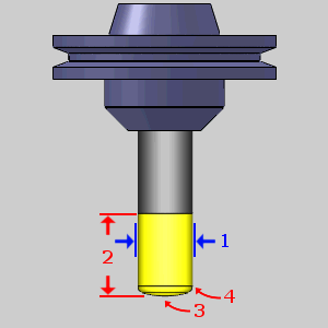
Mill
Endmill Rough
Tool Parameters
|
|
Tool Holder
- Holder
Label - displays the name of the associated tool holder.
When blank, no tool holder is associated.
- Assign/Remove Tool Holder - When no tool holder has been assigned, the Holder Label will be blank, and the button will read: Assign Tool Holder. This will open The Milling Tool Holder Library to allow you to select, or create a tool holder to associate with the selected tool. Once a tool holder has been assigned, the button will read: Remove Tool Holder. This will remove the association between the tool holder and the selected tool.
Feeds and Speeds
- Use System
Feeds and Speeds
Select this check
box to automatically calculate the feeds and speeds. Clear this check
box to type feeds and speeds values manually. - Spindle Speed/RPM - is the revolutions
per minute of the spindle.
- Plunge Feedrate - is the
downward feedrate. This value is linked to the Plunge Feed per Tooth.
- Cutting Feedrate - is the feedrate for feed moves.
Custom Geometry
- Assign Tool Geometry - hides the Tool Library and opens the Tool Shape Picking dialog to allow you to select geometry from the graphics area to assign as the shape of the tool. You can learn more about assigning custom tools in the Assigning Custom Tools topic.
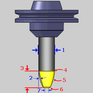
Endmill Finish
Tool Parameters
|
|
Tool Holder
- Holder
Label - displays the name of the associated tool holder.
When blank, no tool holder is associated.
- Assign/Remove Tool Holder - When no tool holder has been assigned, the Holder Label will be blank, and the button will read: Assign Tool Holder. This will open The Milling Tool Holder Library to allow you to select, or create a tool holder to associate with the selected tool. Once a tool holder has been assigned, the button will read: Remove Tool Holder. This will remove the association between the tool holder and the selected tool.
Feeds and Speeds
- Use System
Feeds and Speeds
Select this check
box to automatically calculate the feeds and speeds. Clear this check
box to type feeds and speeds values manually. - Spindle Speed/RPM - is the revolutions
per minute of the spindle.
- Plunge Feedrate - is the
downward feedrate. This value is linked to the Plunge Feed per Tooth.
- Cutting Feedrate - is the feedrate for feed moves.
Custom Geometry
- Assign Tool Geometry - hides the Tool Library and opens the Tool Shape Picking dialog to allow you to select geometry from the graphics area to assign as the shape of the tool. You can learn more about assigning custom tools in the Assigning Custom Tools topic.
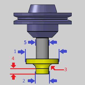
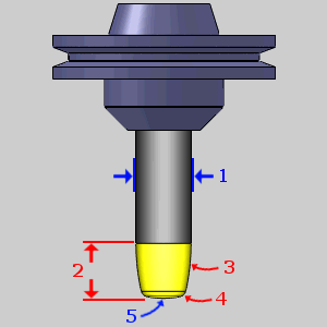
Chamfer Mill
Tool Parameters
|
|
Tool Holder
- Holder
Label - displays the name of the associated tool holder.
When blank, no tool holder is associated.
- Assign/Remove Tool Holder - When no tool holder has been assigned, the Holder Label will be blank, and the button will read: Assign Tool Holder. This will open The Milling Tool Holder Library to allow you to select, or create a tool holder to associate with the selected tool. Once a tool holder has been assigned, the button will read: Remove Tool Holder. This will remove the association between the tool holder and the selected tool.
Feeds and Speeds
- Use System
Feeds and Speeds
Select this check
box to automatically calculate the feeds and speeds. Clear this check
box to type feeds and speeds values manually. - Spindle Speed/RPM - is the revolutions
per minute of the spindle.
- Plunge Feedrate - is the downward feedrate. This value is linked to the Plunge Feed per Tooth.
Custom Geometry
- Assign Tool Geometry - hides the Tool Library and opens the Tool Shape Picking dialog to allow you to select geometry from the graphics area to assign as the shape of the tool. You can learn more about assigning custom tools in the Assigning Custom Tools topic.
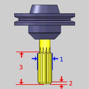
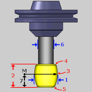
Corner-Round
When defining a corner rounding tool, the diameter must be greater than or equal to the small diameter plus twice the corner radius.
Diameter >= Small Diameter + (Corner Radius * 2)
If you enter values that do not fit this equation, an error message displays.
Tip: When defining a corner rounding tool, if the Diameter is greater than the current/default value, set the Diameter value first. This allows you to avoid receiving the error message. If the Diameter is less than the current/default value, set the Corner Radius first to avoid the error message.
Tool Parameters
|
|
Tool Holder
- Holder
Label - displays the name of the associated tool holder.
When blank, no tool holder is associated.
- Assign/Remove Tool Holder - When no tool holder has been assigned, the Holder Label will be blank, and the button will read: Assign Tool Holder. This will open The Milling Tool Holder Library to allow you to select, or create a tool holder to associate with the selected tool. Once a tool holder has been assigned, the button will read: Remove Tool Holder. This will remove the association between the tool holder and the selected tool.
Feeds and Speeds
- Use System
Feeds and Speeds
Select this check
box to automatically calculate the feeds and speeds. Clear this check
box to type feeds and speeds values manually. - Spindle Speed/RPM - is the revolutions
per minute of the spindle.
- Plunge Feedrate - is the downward feedrate. This value is linked to the Plunge Feed per Tooth.
Custom Geometry
- Assign Tool Geometry - hides the Tool Library and opens the Tool Shape Picking dialog to allow you to select geometry from the graphics area to assign as the shape of the tool. You can learn more about assigning custom tools in the Assigning Custom Tools topic.
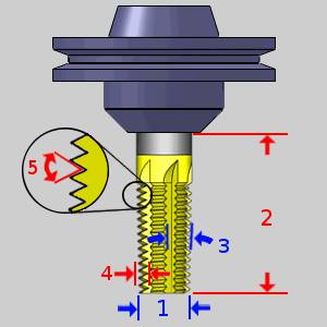
Thread Mill
Tool Parameters
|
|
Tool Holder
- Holder
Label - displays the name of the associated tool holder.
When blank, no tool holder is associated.
- Assign/Remove Tool Holder - When no tool holder has been assigned, the Holder Label will be blank, and the button will read: Assign Tool Holder. This will open The Milling Tool Holder Library to allow you to select, or create a tool holder to associate with the selected tool. Once a tool holder has been assigned, the button will read: Remove Tool Holder. This will remove the association between the tool holder and the selected tool.
Feeds and Speeds
- Use System
Feeds and Speeds
Select this check
box to automatically calculate the feeds and speeds. Clear this check
box to type feeds and speeds values manually. - Spindle Speed/RPM - is the revolutions
per minute of the spindle.
- Plunge Feedrate - is the
downward feedrate. This value is linked to the Plunge Feed per Tooth.
- Cutting Feedrate - is the feedrate for feed moves.
Custom Geometry
- Assign Tool Geometry - hides the Tool Library and opens the Tool Shape Picking dialog to allow you to select geometry from the graphics area to assign as the shape of the tool. You can learn more about assigning custom tools in the Assigning Custom Tools topic.
Single Point Thread
Tool Parameters
|
|
Tool Holder
- Holder
Label - displays the name of the associated tool holder.
When blank, no tool holder is associated.
- Assign/Remove Tool Holder - When no tool holder has been assigned, the Holder Label will be blank, and the button will read: Assign Tool Holder. This will open The Milling Tool Holder Library to allow you to select, or create a tool holder to associate with the selected tool. Once a tool holder has been assigned, the button will read: Remove Tool Holder. This will remove the association between the tool holder and the selected tool.
Feeds and Speeds
- Use System
Feeds and Speeds
Select this check
box to automatically calculate the feeds and speeds. Clear this check
box to type feeds and speeds values manually. - Spindle Speed/RPM - is the revolutions
per minute of the spindle.
- Plunge Feedrate - is the
downward feedrate. This value is linked to the Plunge Feed per Tooth.
- Cutting Feedrate - is the feedrate for feed moves.
Custom Geometry
- Assign Tool Geometry - hides the Tool Library and opens the Tool Shape Picking dialog to allow you to select geometry from the graphics area to assign as the shape of the tool. You can learn more about assigning custom tools in the Assigning Custom Tools topic.
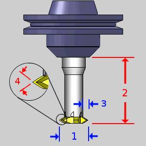
V-Tool
Tool Parameters
|
|
Tool Holder
- Holder
Label - displays the name of the associated tool holder.
When blank, no tool holder is associated.
- Assign/Remove Tool Holder - When no tool holder has been assigned, the Holder Label will be blank, and the button will read: Assign Tool Holder. This will open The Milling Tool Holder Library to allow you to select, or create a tool holder to associate with the selected tool. Once a tool holder has been assigned, the button will read: Remove Tool Holder. This will remove the association between the tool holder and the selected tool.
Feeds and Speeds
- Use System
Feeds and Speeds
Select this check
box to automatically calculate the feeds and speeds. Clear this check
box to type feeds and speeds values manually. - Spindle Speed/RPM - is the revolutions
per minute of the spindle.
- Plunge Feedrate - is the
downward feedrate. This value is linked to the Plunge Feed per Tooth.
- Cutting Feedrate - is the feedrate for feed moves.
Custom Geometry
- Assign Tool Geometry - hides the Tool Library and opens the Tool Shape Picking dialog to allow you to select geometry from the graphics area to assign as the shape of the tool. You can learn more about assigning custom tools in the Assigning Custom Tools topic.
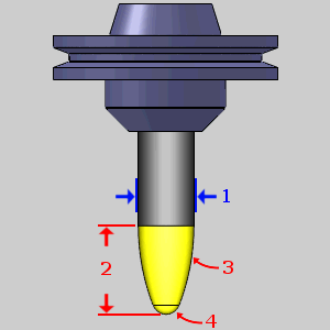
Tapered
Tool Parameters
|
|
Tool Holder
- Holder
Label - displays the name of the associated tool holder.
When blank, no tool holder is associated.
- Assign/Remove Tool Holder - When no tool holder has been assigned, the Holder Label will be blank, and the button will read: Assign Tool Holder. This will open The Milling Tool Holder Library to allow you to select, or create a tool holder to associate with the selected tool. Once a tool holder has been assigned, the button will read: Remove Tool Holder. This will remove the association between the tool holder and the selected tool.
Feeds and Speeds
- Use System
Feeds and Speeds
Select this check
box to automatically calculate the feeds and speeds. Clear this check
box to type feeds and speeds values manually. - Spindle Speed/RPM - is the revolutions
per minute of the spindle.
- Plunge Feedrate - is the
downward feedrate. This value is linked to the Plunge Feed per Tooth.
- Cutting Feedrate - is the feedrate for feed moves.
Custom Geometry
- Assign Tool Geometry - hides the Tool Library and opens the Tool Shape Picking dialog to allow you to select geometry from the graphics area to assign as the shape of the tool. You can learn more about assigning custom tools in the Assigning Custom Tools topic.
T-Cutter
Tool Parameters
|
|
Tool Holder
- Holder
Label - displays the name of the associated tool holder.
When blank, no tool holder is associated.
- Assign/Remove Tool Holder - When no tool holder has been assigned, the Holder Label will be blank, and the button will read: Assign Tool Holder. This will open The Milling Tool Holder Library to allow you to select, or create a tool holder to associate with the selected tool. Once a tool holder has been assigned, the button will read: Remove Tool Holder. This will remove the association between the tool holder and the selected tool.
Feeds and Speeds
- Use System
Feeds and Speeds
Select this check
box to automatically calculate the feeds and speeds. Clear this check
box to type feeds and speeds values manually. - Spindle Speed/RPM - is the revolutions
per minute of the spindle.
- Plunge Feedrate - is the downward feedrate. This value is linked to the Plunge Feed per Tooth.
Custom Geometry
- Assign Tool Geometry - hides the Tool Library and opens the Tool Shape Picking dialog to allow you to select geometry from the graphics area to assign as the shape of the tool. You can learn more about assigning custom tools in the Assigning Custom Tools topic.
Dove Mill
Tool Parameters
|
|
Tool Holder
- Holder
Label - displays the name of the associated tool holder.
When blank, no tool holder is associated.
- Assign/Remove Tool Holder - When no tool holder has been assigned, the Holder Label will be blank, and the button will read: Assign Tool Holder. This will open The Milling Tool Holder Library to allow you to select, or create a tool holder to associate with the selected tool. Once a tool holder has been assigned, the button will read: Remove Tool Holder. This will remove the association between the tool holder and the selected tool.
Feeds and Speeds
- Use System
Feeds and Speeds
Select this check
box to automatically calculate the feeds and speeds. Clear this check
box to type feeds and speeds values manually. - Spindle Speed/RPM - is the revolutions
per minute of the spindle.
- Plunge Feedrate - is the
downward feedrate. This value is linked to the Plunge Feed per Tooth.
- Cutting Feedrate - is the feedrate for feed moves.
Custom Geometry
- Assign Tool Geometry - hides the Tool Library and opens the Tool Shape Picking dialog to allow you to select geometry from the graphics area to assign as the shape of the tool. You can learn more about assigning custom tools in the Assigning Custom Tools topic.
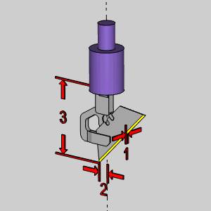
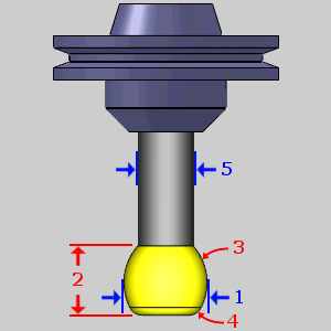
Lollipop
Tool Parameters
|
|
Tool Holder
- Holder
Label - displays the name of the associated tool holder.
When blank, no tool holder is associated.
- Assign/Remove Tool Holder - When no tool holder has been assigned, the Holder Label will be blank, and the button will read: Assign Tool Holder. This will open The Milling Tool Holder Library to allow you to select, or create a tool holder to associate with the selected tool. Once a tool holder has been assigned, the button will read: Remove Tool Holder. This will remove the association between the tool holder and the selected tool.
Feeds and Speeds
- Use System
Feeds and Speeds
Select this check
box to automatically calculate the feeds and speeds. Clear this check
box to type feeds and speeds values manually. - Spindle Speed/RPM - is the revolutions
per minute of the spindle.
- Plunge Feedrate - is the downward feedrate. This value is linked to the Plunge Feed per Tooth.
Custom Geometry
- Assign Tool Geometry - hides the Tool Library and opens the Tool Shape Picking dialog to allow you to select geometry from the graphics area to assign as the shape of the tool. You can learn more about assigning custom tools in the Assigning Custom Tools topic.
Drag Knife
Tool Parameters
|
|
Tool Holder
- Holder
Label - displays the name of the associated tool holder.
When blank, no tool holder is associated.
- Assign/Remove Tool Holder - When no tool holder has been assigned, the Holder Label will be blank, and the button will read: Assign Tool Holder. This will open The Milling Tool Holder Library to allow you to select, or create a tool holder to associate with the selected tool. Once a tool holder has been assigned, the button will read: Remove Tool Holder. This will remove the association between the tool holder and the selected tool.
Feeds and Speeds
- Use System
Feeds and Speeds
Select this check
box to automatically calculate the feeds and speeds. Clear this check
box to type feeds and speeds values manually. - Plunge Feedrate - is the
downward feedrate. This value is linked to the Plunge Feed per Tooth.
- Cutting Feedrate - is the feedrate for feed moves.
Barrel-Standard
Note: To get a more in depth look at the barrel tool type, see the Barrel Mills topic.
Tool Parameters
|
|
Tool Holder
- Holder
Label - displays the name of the associated tool holder.
When blank, no tool holder is associated.
- Assign/Remove Tool Holder - When no tool holder has been assigned, the Holder Label will be blank, and the button will read: Assign Tool Holder. This will open The Milling Tool Holder Library to allow you to select, or create a tool holder to associate with the selected tool. Once a tool holder has been assigned, the button will read: Remove Tool Holder. This will remove the association between the tool holder and the selected tool.
Feeds and Speeds
- Use System
Feeds and Speeds
Select this check
box to automatically calculate the feeds and speeds. Clear this check
box to type feeds and speeds values manually. - Spindle Speed/RPM - is the revolutions
per minute of the spindle.
- Plunge Feedrate - is the downward feedrate. This value is linked to the Plunge Feed per Tooth.
Custom Geometry
- Assign Tool Geometry - hides the Tool Library and opens the Tool Shape Picking dialog to allow you to select geometry from the graphics area to assign as the shape of the tool. You can learn more about assigning custom tools in the Assigning Custom Tools topic.
Important: The following rules apply when creating a valid tool shape:
• Profile radius must be greater than the corner radius
• Diameter must be equal to or greater than the upper diameter
Barrel-Advanced
Note: The Advanced barrel type has several parameters that present a choice on how you would like to define the tool. To get a more in depth look at these options, see the Barrel Mills topic.
Tool Parameters
Important: (8): This value will typically be negative, unless the arc and its center are on the same side of the revolved axis. See Barrel Mills.
|
|
Tool Holder
- Holder
Label - displays the name of the associated tool holder.
When blank, no tool holder is associated.
- Assign/Remove Tool Holder - When no tool holder has been assigned, the Holder Label will be blank, and the button will read: Assign Tool Holder. This will open The Milling Tool Holder Library to allow you to select, or create a tool holder to associate with the selected tool. Once a tool holder has been assigned, the button will read: Remove Tool Holder. This will remove the association between the tool holder and the selected tool.
Feeds and Speeds
- Use System
Feeds and Speeds
Select this check
box to automatically calculate the feeds and speeds. Clear this check
box to type feeds and speeds values manually. - Spindle Speed/RPM - is the revolutions
per minute of the spindle.
- Plunge Feedrate - is the downward feedrate. This value is linked to the Plunge Feed per Tooth.
Custom Geometry
- Assign Tool Geometry - hides the Tool Library and opens the Tool Shape Picking dialog to allow you to select geometry from the graphics area to assign as the shape of the tool. You can learn more about assigning custom tools in the Assigning Custom Tools topic.
Important: The following rules apply when creating a valid tool shape:
• Diameter must be greater than or equal to the Shaft diameter
• Diameter must be greater than the reference diameter for the barrel mill
• Profile position by (Radial): Distance (M)
• Profile radius must be greater than the radial distance of the profile
• Profile position by (Axial): Distance (M)
• Profile radius must be greater than the axial distance of the profile
• Profile position by (Axial): Reference diameter
• Profile radius must be greater than the radial distance of the profile plus the reference radius
• Flute height by: Upper diameter
• Profile radius must be greater than the radial distance of the profile plus the upper radius
• Flute height by: Length
• Profile radius must be greater than flute length minus the axial distance of profile
Barrel-Tangent
Note: To get a more in depth look at the barrel tool type, see the Barrel Mills topic.
Tool Parameters
|
|
Tool Holder
- Holder
Label - displays the name of the associated tool holder.
When blank, no tool holder is associated.
- Assign/Remove Tool Holder - When no tool holder has been assigned, the Holder Label will be blank, and the button will read: Assign Tool Holder. This will open The Milling Tool Holder Library to allow you to select, or create a tool holder to associate with the selected tool. Once a tool holder has been assigned, the button will read: Remove Tool Holder. This will remove the association between the tool holder and the selected tool.
Feeds and Speeds
- Use System
Feeds and Speeds
Select this check
box to automatically calculate the feeds and speeds. Clear this check
box to type feeds and speeds values manually. - Spindle Speed/RPM - is the revolutions
per minute of the spindle.
- Plunge Feedrate - is the downward feedrate. This value is linked to the Plunge Feed per Tooth.
Custom Geometry
- Assign Tool Geometry - hides the Tool Library and opens the Tool Shape Picking dialog to allow you to select geometry from the graphics area to assign as the shape of the tool. You can learn more about assigning custom tools in the Assigning Custom Tools topic.
Barrel-Lens
Note: To get a more in depth look at the barrel tool type, see the Barrel Mills topic.
Tool Parameters
|
|
Tool Holder
- Holder
Label - displays the name of the associated tool holder.
When blank, no tool holder is associated.
- Assign/Remove Tool Holder - When no tool holder has been assigned, the Holder Label will be blank, and the button will read: Assign Tool Holder. This will open The Milling Tool Holder Library to allow you to select, or create a tool holder to associate with the selected tool. Once a tool holder has been assigned, the button will read: Remove Tool Holder. This will remove the association between the tool holder and the selected tool.
Feeds and Speeds
- Use System
Feeds and Speeds
Select this check
box to automatically calculate the feeds and speeds. Clear this check
box to type feeds and speeds values manually. - Spindle Speed/RPM - is the revolutions
per minute of the spindle.
- Plunge Feedrate - is the downward feedrate. This value is linked to the Plunge Feed per Tooth.
Custom Geometry
- Assign Tool Geometry - hides the Tool Library and opens the Tool Shape Picking dialog to allow you to select geometry from the graphics area to assign as the shape of the tool. You can learn more about assigning custom tools in the Assigning Custom Tools topic.
Important: The following rules apply when creating a valid tool shape:
• Convex Tip Radius must be greater than, or equal to, half of the tool Diameter
Barrel-Taper
Note: To get a more in depth look at the barrel tool type, see the Barrel Mills topic.
Tool Parameters
|
|
Tool Holder
- Holder
Label - displays the name of the associated tool holder.
When blank, no tool holder is associated.
- Assign/Remove Tool Holder - When no tool holder has been assigned, the Holder Label will be blank, and the button will read: Assign Tool Holder. This will open The Milling Tool Holder Library to allow you to select, or create a tool holder to associate with the selected tool. Once a tool holder has been assigned, the button will read: Remove Tool Holder. This will remove the association between the tool holder and the selected tool.
Feeds and Speeds
- Use System
Feeds and Speeds
Select this check
box to automatically calculate the feeds and speeds. Clear this check
box to type feeds and speeds values manually. - Spindle Speed/RPM - is the revolutions
per minute of the spindle.
- Plunge Feedrate - is the downward feedrate. This value is linked to the Plunge Feed per Tooth.
Custom Geometry
- Assign Tool Geometry - hides the Tool Library and opens the Tool Shape Picking dialog to allow you to select geometry from the graphics area to assign as the shape of the tool. You can learn more about assigning custom tools in the Assigning Custom Tools topic.
Important: The following rules apply when creating a valid tool shape:
• Taper angle must be greater than 0.1, and less than 89
• Profile Radius must be greater than half of the Diameter
• Corner Radius must be less than half of the Diameter
• Upper Radius must not exceed half of the Diameter
Barrel-Double
Note: To get a more in depth look at the barrel tool type, see the Barrel Mills topic.
Tool Parameters
|
|
Tool Holder
- Holder
Label - displays the name of the associated tool holder.
When blank, no tool holder is associated.
- Assign/Remove Tool Holder - When no tool holder has been assigned, the Holder Label will be blank, and the button will read: Assign Tool Holder. This will open The Milling Tool Holder Library to allow you to select, or create a tool holder to associate with the selected tool. Once a tool holder has been assigned, the button will read: Remove Tool Holder. This will remove the association between the tool holder and the selected tool.
Feeds and Speeds
- Use System
Feeds and Speeds
Select this check
box to automatically calculate the feeds and speeds. Clear this check
box to type feeds and speeds values manually. - Spindle Speed/RPM - is the revolutions
per minute of the spindle.
- Plunge Feedrate - is the downward feedrate. This value is linked to the Plunge Feed per Tooth.
Custom Geometry
- Assign Tool Geometry - hides the Tool Library and opens the Tool Shape Picking dialog to allow you to select geometry from the graphics area to assign as the shape of the tool. You can learn more about assigning custom tools in the Assigning Custom Tools topic.
Barrel-Section
Note: To get a more in depth look at the barrel tool type, see the Barrel Mills topic.
Tool Parameters
|
|
Tool Holder
- Holder
Label - displays the name of the associated tool holder.
When blank, no tool holder is associated.
- Assign/Remove Tool Holder - When no tool holder has been assigned, the Holder Label will be blank, and the button will read: Assign Tool Holder. This will open The Milling Tool Holder Library to allow you to select, or create a tool holder to associate with the selected tool. Once a tool holder has been assigned, the button will read: Remove Tool Holder. This will remove the association between the tool holder and the selected tool.
Feeds and Speeds
- Use System
Feeds and Speeds
Select this check
box to automatically calculate the feeds and speeds. Clear this check
box to type feeds and speeds values manually. - Spindle Speed/RPM - is the revolutions
per minute of the spindle.
- Plunge Feedrate - is the downward feedrate. This value is linked to the Plunge Feed per Tooth.
Custom Geometry
- Assign Tool Geometry - hides the Tool Library and opens the Tool Shape Picking dialog to allow you to select geometry from the graphics area to assign as the shape of the tool. You can learn more about assigning custom tools in the Assigning Custom Tools topic.
Important: The following rules apply when creating a valid tool shape:
• Upper Corner Radius must be smaller than the Flute Length
• Lower Corner Radius must be smaller than the Flute Length
• Upper Corner Radius must be smaller than the Profile Radius
• Lower Corner Radius must be smaller than the Profile Radius
• Distance(M) Axial must be lower than the Flute Length
• Profile Radius must be greater than half of the Diameter
• Profile Radius must be greater than Distance(M) Axial
• Diameter must be greater than the Shaft Diameter
Turning
Lathe Rough / Finish / Boring
Tool
- Tool
Label - adds a name to the tool, in the tool list,
that allows you to easily identify the tool.
- Tool Number - sets the assigned tool number
- Offset Register - sets the register on the machine that
stores the diameter offset values for the tool.
Insert
Note: The following Parameters section differs depending on whether the System Shape or the Custom Shape radio button is selected. Below you will find a separate Parameters section for each option.
-
 System Shape - uses the following parameters to set the shape
designation of the insert.
System Shape - uses the following parameters to set the shape
designation of the insert.
Parameters
| • Shape - dictates the shape designation of the insert. | • Clearance - dictates the clearance designation of the insert. | |||||||||||||||||||||||||||||||||||||||||||||||||||||||||||||||||||||||
|
|


- Tolerance - sets
the tolerance designation of the insert. This does not affect
toolpath or output.
- Type - sets the type designation of the insert. This does not affect toolpath or output.
|
• Reference Point - allows you to choose an alignment of the reference point to the insert. |
||||||
|
- Nose Radius - sets
the radius of the tool nose.
- IC Diameter - sets the internal circumference
of the insert.
- Thickness - dictates the distance between the front cutting edge to the back of the insert.
-
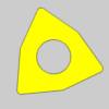
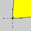
 Custom Shape - allows you to select geometry from the graphics area to define the shape of the insert.
Parameters
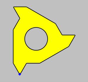
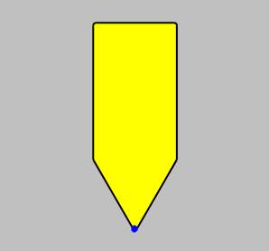
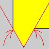
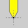
- Assign Tool Insert - When
Custom Shape is selected, clicking the Assign Tool Insert button will
hide the Tool Library and allow you to select Tool Insert geometry, as seen below,
from the graphics area.
Important: When
assigning insert geometry, be sure to have the reference point
defined as a point, and any interior geometry drawn as a dotted
line as shown. For more information, see the Assigning Lathe Tool Inserts topic.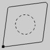
- Nose Radius - sets the
radius of the tool nose.
- IC Diameter - sets the internal circumference of
the insert.
- Thickness - dictates the distance between the front cutting edge to the back of the insert.
Holder
- Edit Tool Holder - will launch the Tool Holder Definition dialog box to allow you to specify measurements for the holder, or select geometry from the Workspace in order to define the holder.
Feeds and Speeds
- Use Manual Feeds
and Speeds
- Default Feeds and Speeds are used. - Selecting this check box will give you access to the
following parameters. These will allow you to set specific Feeds and Speeds
for the insert. When the insert is used in the Lathe Wizard, these will
be the values that are automatically entered for the tool. -
RPM - sets the feeds and speeds to revolutions
per minute.
- CSS - sets the feeds and speeds to a constant
surface speed.
- Maximum
RPM - sets the limits of the spindle speed in the posted
NC program.
- Spindle
RPM/SFM - sets the spindle speed for the feature in revolutions
per minute or the surface feet per minute based on the selected
RPM/CSS option.
- Feedrate
- sets the feedrate for the feature.
- Maximum
RPM - sets the limits of the spindle speed in the posted
NC program.
Lathe Groove / Cutoff
Tool
- Tool
Label - adds a name to the tool, in the tool list,
that allows you to easily identify the tool.
- Tool Number - sets the assigned tool number
- Offset Register - sets the register on the machine that
stores the diameter offset values for the tool.
Insert
Note: The following Parameters section differs depending on whether the System Shape or the Custom Shape radio button is selected. Below you will find a separate Parameters section for each option.
-
System Shape - uses the following parameters to set the shape
designation of the insert.
Parameters
- Tool Width - sets the width
of the insert.
- Tool Length - sets the
length of the insert.
- Side Angle - sets the side
angle of the insert.
- Tip Angle - sets the tip
angle of the insert.
- Reference Point - allows you to choose an alignment of the reference point to the insert, as seen below:
|
Left Corner |
Tip |
Right Corner |
|
|
|
|
- Nose Radius - sets
the radius between the side and bottom of the insert.
- Thickness - dictates the distance between the front cutting edge to the back of the insert.
-
Custom Shape - allows you to select geometry from the graphics area to define the shape of the insert.
Parameters
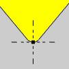
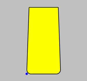
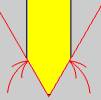
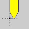
- Assign Tool Insert - When
Custom Shape is selected, clicking the Assign Tool Insert button will
hide the Tool Library and allow you to select Tool Insert geometry, as seen below,
from the graphics area.
Important: When
assigning insert geometry, be sure to have the reference point
defined as a point. For more information, see the Assigning Lathe Tool Inserts topic.
- Tool Nose Radius - sets the
radius of the tool nose.
- Thickness - dictates the distance between the front cutting edge to the back of the insert.
Holder
- Edit Tool Holder - will launch the Tool Holder Definition dialog box to allow you to specify measurements for the holder, or select geometry from the Workspace in order to define the holder.
Feeds and Speeds
- Use Manual Feeds
and Speeds
- Default Feeds and Speeds are used. - Selecting this check box will give you access to the
following parameters. These will allow you to set specific Feeds and Speeds
for the insert. When the insert is used in the Lathe Wizard, the values below will
be the values that are automatically entered for the tool. -
RPM - sets the feeds and speeds to revolutions
per minute.
- CSS - sets the feeds and speeds to a constant
surface speed.
- Maximum
RPM - sets the limits of the spindle speed in the posted
NC program.
- Spindle
RPM/SFM - sets the spindle speed for the feature in revolutions
per minute or the surface feet per minute based on the selected
RPM/CSS option.
- Feedrate - sets the feedrate for the feature.
- Maximum
RPM - sets the limits of the spindle speed in the posted
NC program.
Parameters
- Home Position Z - sets the
Home Position in Z for the tool.
- Home Position X - sets the Home Position in X for the tool.
- Reverse Sign
- With this check box cleared, the output of the X value maintains its default behavior. A move toward the center of rotation will be output as a negative
move and a move away from the center of rotation a positive move. - With this check box selected, the output of the X value reverses. A move toward the center of rotation will be output as a negative
move and a move away from the center of rotation a positive move.
Lathe Thread
| Shape: LayDown | Shape: Top Notch |
|
|
Tool
The Tool data differs slightly based on the Shape chosen.
- Tool
Label - adds a name to the tool, in the tool list,
that allows you to easily identify the tool.
- Tool Number - sets the assigned tool number
- Offset Register - sets the register on the machine that stores the diameter offset values for the tool.
Insert
Note: The following Parameters section differs depending on whether the System Shape or the Custom Shape radio button is selected. Below you will find a separate Parameters section for each option.
-
System Shape - uses the following parameters to set the shape
designation of the insert.
Parameters
- Shape - sets the shape designation of the insert.
|
Lay Down |
Top Notch |
|
|
|
- Tool Angle - sets the angle of the insert.
|
Lay Down |
Top Notch |
|
|
|
- Tip Height - sets
the tip height of the insert when the Lay Down Shape is selected.
- Height - sets the
height of the insert when the Top Notch Shape is selected.
- Width - sets the width of the insert when the Top Notch Shape is selected.
- Reference Point - allows you to choose an alignment of the reference point to the insert.
| Reference Point: Corner | Reference Point: Tip | |||
| Lay Down |
Top Notch |
Lay Down |
Top Notch | |
|
|
|
|
|
- Tool Nose Radius - sets
the radius of the tool nose.
- IC Diameter - sets the internal circumference of the insert when the Lay Down Shape is selected.
- Thickness - dictates the distance between the front cutting edge to the back of the insert.
-
Custom Shape - allows you to select geometry from the graphics area to define the shape of the insert.
Parameters
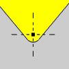
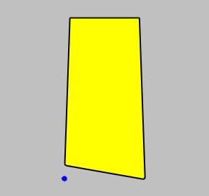
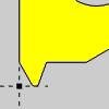
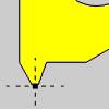
- Assign Tool Insert - When
Custom Shape is selected, clicking the Assign Tool Insert button will
hide the Tool Library and allow you to select Tool Insert geometry, as seen below,
from the graphics area.
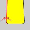
Important: When
assigning insert geometry, be sure to have the reference point
defined as a point, and any interior geometry drawn as a dotted
line as shown. For more information, see the Assigning Lathe Tool Inserts topic.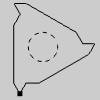
- Nose Radius - sets the
radius of the tool nose.
- IC Diameter - sets the internal circumference of
the insert.
- Thickness - dictates the distance between the front cutting edge to the back of the insert.
Holder
- Edit Tool Holder - will launch the Tool Holder Definition dialog box to allow you to specify measurements for the holder, or select geometry from the Workspace in order to define the holder.
Feeds and Speeds
- Use Manual Feeds
and Speeds
- Default Feeds and Speeds are used. - Selecting this check box will give you access to the
following parameters. These will allow you to set specific Feeds and Speeds
for the insert. When the insert is used in the Lathe Wizard, the values below will
be the values that are automatically entered for the tool. -
RPM - sets the feeds and speeds to revolutions
per minute.
- CSS - sets the feeds and speeds to a constant
surface speed.
- Maximum
RPM - sets the limits of the spindle speed in the posted
NC program.
- Spindle
RPM/SFM - sets the spindle speed for the feature in revolutions
per minute or the surface feet per minute based on the selected
RPM/CSS option.
- Feedrate - sets the feedrate for the feature.
- Maximum
RPM - sets the limits of the spindle speed in the posted
NC program.
Parameters
- Home Position Z - sets the
Home Position in Z for the tool.
- Home Position X - sets the Home Position in X for the tool.
- Reverse Sign
- With this check box cleared, the output of the X value maintains its default behavior. A move toward the center of rotation will be output as a negative
move and a move away from the center of rotation a positive move. - With this check box selected, the output of the X value reverses. A move toward the center of rotation will be output as a negative
move and a move away from the center of rotation a positive move.
Related Topics
The Tool Library Functionality
Next Topic
Once the Tool variables have been set, clicking Next>> will take you to the next page of the given operation. To move the appropriate next topic, click the type of feature that has been chosen below and then the link for the desired operation.
Center Drill Parameters
Drill Operation Parameters
Chamfer Drill Parameters
Chamfer Mill Patterns
Ream Parameters
Bore Parameters
Rolling Tap Parameters
Counterbore Drill Parameters
Counterbore Mill Parameters
Tap Parameters
Rolling Tap Parameters
Facing Patterns
Profile Rough Patterns
Profile Finish Patterns
Pocket Patterns
Facing Patterns
Engrave Parameters
Chamfer Mill Patterns
Plunge Rough (2 Axis) Patterns
Corner Rounding Patterns
Z Level Rough Patterns
Z Level Finish Patterns
Planar Patterns
Spiral Patterns
Radial Patterns
Plunge Rough Patterns
Advanced Rough Patterns
Flatlands Parameters
Equidistant Patterns
Pencil Parameters
Advanced Planar Patterns
Project Curves Patterns
Advanced Z Level Finish Patterns
4 Axis Rotary Patterns
Mill Thread Pattern
3 Axis Wireframe Parameters
Thread Parameters
Cutoff Parameters
Stock Handling Parameters