


Shape Library Parameters
Introduction
This topic provides a reference to all available shapes in the Shape Library and the parameters used to create them.
|
Important: When defining the parameters for any shape, the CAD preview is removed when invalid values are entered. If you have entered all values for the shape and the CAD preview isn't visible, confirm you have properly defined the parameters as shown in the Data Entry Manager. All of the shape diagrams and dimensions are provided in this topic.
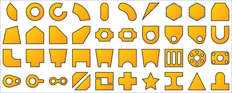
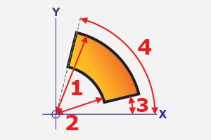
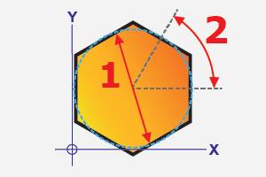
Disk Slice (Shape 1)
|
Parameters
1 - the outside diameter.
2 - the angle range measured clockwise starting at 270.00 degrees. This is a positive angle between 0.00 and 360.00 degrees.
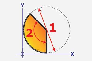
Ring (Shape 2)
|
Parameters
1 - the outside diameter.
2 - the inside diameter.
Note: P1 must be greater than P2. If P2 is zero then no center hole is created.
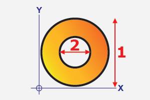
Cut Ring (Shape 3)
|
Parameters
1 - the outside diameter.
2 - the inside diameter.
3 - the angle range of the slot measured counterclockwise starting at 0.00 degrees.
Tip: If using a large value for P3, it may be better to use Ring Segment. The Ring Segment uses the arc center as the origin and it is calculated with a smaller bounding box than Cut Ring.
Ring Segment (Shape 4)
|
Parameters
1 - the outer radius.
2 - the inner radius.
3 - the starting angle measured from zero degrees or the X-axis of the shape origin.
4 - the ending angle measured from zero degrees or the X-axis of the shape origin.
Note: The angles for P3 and P4 are positive or negative values between 0.00 and 360.00 degrees.
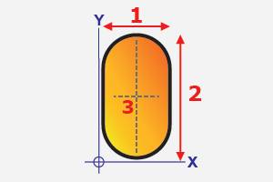
Slot (Shape 5)
|
Parameters
1 - the length or X-axis dimension from the shape origin. This value should be less than P2.
2 - the width or Y-axis dimension from the shape origin. This value should be greater than P1.
3 - the rotation angle about the center of the slot. This is used to define the orientation of the slot. A value of 0.00 degrees creates a vertical slot and a value of 90.00 degrees creates a horizontal slot.
Tip: While P3 rotates the slot from the center, you can use the Rotation Angle parameter to rotate the slot about the origin (lower-left corner) of the shape.
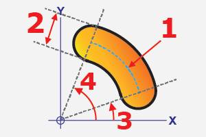
Curved Slot (Shape 6)
|
Parameters
1 - the radius or distance from the shape origin to the center of the slot.
2 - the width of the slot centered on the radius (P1).
3 - the start angle measured from zero degrees or the X-axis of the shape origin.
4 - the end angle measured from zero degrees or the X-axis of the shape origin.
Note: For P3 and P4, the angle is a positive or negative value between 0.00 and 360.00 degrees. The angle is measured to the arc center at the ends of the slot as shown in the diagram.
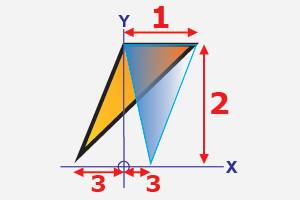
Triangle (Shape 7)
|
Parameters
1 - the length or X-axis dimension from the shape origin.
2 - the width or Y-axis dimension from the shape origin.
3 - the X-axis location of the lower point.
Inner Polygon (Shape 8)
|
Parameters
1 - the inside diameter of the polygon. All sides are created tangent to this diameter, so this is the distance between any two parallel sides.
2- is the amount of rotation in degrees around the shape center. The rotation angle is applied counterclockwise from zero degrees (3 o'clock).
Number of Sides - is the number of sides for the polygon, which must be greater than two.
Tip: One side of the polygon is always created parallel to the Y-axis.
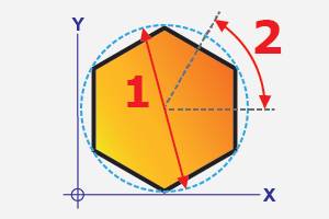
Outer Polygon (Shape 9)
|
Parameters
1 - the outside diameter of the polygon. All sides are created within this diameter (the intersection of any two sides meet this diameter).
2 - is the amount of rotation in degrees around the shape center. The rotation angle is applied counterclockwise from zero degrees (3 o'clock).
Number of Sides - the number of sides for the polygon, which must be greater than two.
Tip: One side of the polygon is always created parallel to the Y-axis.
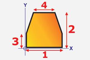
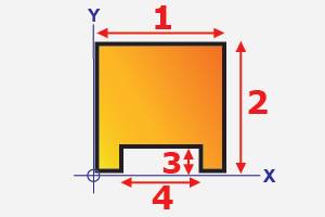
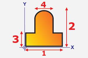
Slanted Support Truss (Shape 10)
|
Parameters
1 - the length or X-axis dimension from the shape origin.
2 - the total width or Y-axis dimension from the shape origin.
3 - the width of the support shoulder, or the Y-axis dimension from the origin to the top of the vertical sides.
4 - the length or X-axis dimension of the top side.
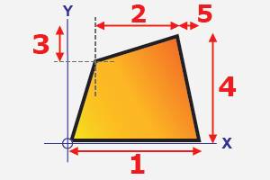
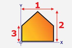
Quad Sided Plate (Shape 11)
|
Parameters
1 - the total length or X-axis dimension from the shape origin.
2 - the length or X-axis dimension of the top side.
3 - the top offset or the Y-axis dimension from the top boundary to the upper-left corner as a positive value. This value must be less than the total width (P4) and can be set to zero.
4 - the total width or Y-axis dimension from the shape origin.
5 - the right offset or the X-axis dimension from the right boundary to the upper-right corner as a positive value, which can be set to zero.
Angular Support Truss (Shape 12)
|
Parameters
1 - the total length or X-axis dimension from the shape origin.
2 - the total width or Y-axis dimension from the shape origin.
3 - the shoulder length or Y-axis dimension from the shape origin to top of the vertical sides.
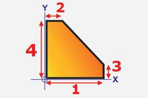
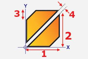
Beveled Rectangle (Shape 13)
|
Parameters
1 - the total length or X-axis dimension from the shape origin.
2 - the length of the top side or X-axis dimension from the shape origin.
3 - the width of the right side or the Y-axis dimension from the shape origin.
4 - the total width or Y-axis dimension from the shape origin.
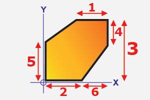
Beam Support (Shape 14)
|
Parameters
1 - the length of the top side or X-axis dimension as a positive value from the right boundary of the shape.
2 - the length of the bottom side or X-axis dimension from the shape origin.
3 - the total width or Y-axis dimension from the shape origin.
4 - the width of the top right side or Y-axis dimension as a positive value from the top boundary of the shape.
5 - the width of the left side or Y-axis dimension from the shape origin.
6 - the length (offset) of the lower angled side or X-axis dimension from the end of P2 to the right boundary of the shape.
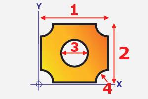
Frame with Round Hole (Shape 15)
|
Parameters
1 - the total length or X-axis dimension from the shape origin.
2 - the total width or Y-axis dimension from the shape origin.
3 - the diameter of the inner hole.
4 - the corner radius of the inverse fillets.
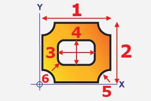
Frame with Rectangular Hole (Shape 16)
|
Parameters
1 - the total length or X-axis dimension from the shape origin.
2 - the total width or Y-axis dimension from the shape origin.
3 - the length or X-axis dimension of the rectangular hole. This is automatically centered on the shape (P1).
4 - the width or Y-axis dimension of the rectangular hole. This is automatically centered on the shape (P2).
5 - the corner radius of the inverse fillets.
6 - the corner radius of the rectangular hole.
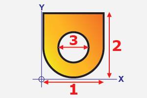
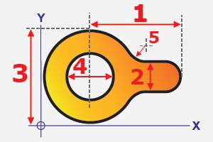
Straight Lug (Shape 17)
|
Parameters
1 - the total length or X-axis dimension from the shape origin.
2 - the total width or Y-axis dimension from the shape origin.
3 - the diameter of the inner hole.
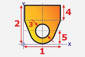
Symmetric Lug (Shape 18)
|
Parameters
1 - the total length or X-axis dimension from the shape origin.
2 - the total width or Y-axis dimension from the shape origin.
3 - the diameter of the inner hole.
4 - the shoulder width or Y-axis dimension from the top of the shape to the bottom of the vertical walls.
5 - the center of the hole or Y-axis dimension from the shape origin.
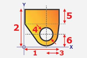
Asymmetric Lug (Shape 19)
|
Parameters
1 - the total length or X-axis dimension from the shape origin.
2 - the total width or Y-axis dimension from the shape origin.
3 - the hole center or X-axis dimension as a positive value from the right boundary (the end of P1). If you set this value to 0.00, the center of the hole is moved to the end of P1, thus changing the shape of the lug.
4 - the diameter of the inner hole.
5 - the shoulder width or Y-axis dimension as a positive value from the top of the shape to the bottom of the vertical walls.
6 - the hole center or Y-axis dimension from the shape origin. (This is also the outer radius of the lug.)
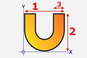
U (Shape 20)
|
Parameters
1 - the total length or X-axis dimension from the shape origin.
2 - the total width or Y-axis dimension from the shape origin.
3 - the length of the shape body.
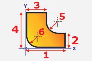
L Bracket (Shape 21)
|
Parameters
1 - the total length or X-axis dimension from the shape origin.
2 - the width of the right side or Y-axis dimension from the shape origin.
3 - the length of the top side or X-axis dimension from the shape origin.
4 - the total width or Y-axis dimension from the shape origin.
5 - the inner (upper right) radius.
6 - the outer (lower left) radius.
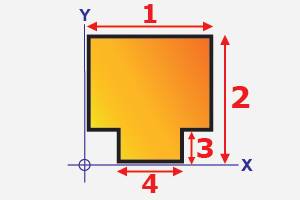
Straight Support with Tab (Shape 22)
|
Parameters
1 - the total length or X-axis dimension from the shape origin.
2 - the total width or Y-axis dimension from the shape origin.
3 - the width of the tab or Y-axis dimension from the shape origin.
4 - the length of the tab or X-axis dimension, which is automatically centered on the shape (or P1).
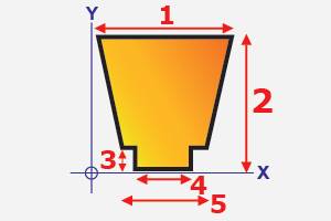
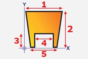
Slanted Support with Tab (Shape 23)
|
Parameters
1 - the total length or X-axis dimension from the shape origin.
2 - the total width or Y-axis dimension from the shape origin.
3 - the width of the tab or Y-axis dimension from the shape origin.
4 - the length of the tab or X-axis dimension, which is automatically centered on the shape (or P1).
5 - the length at the bottom of the support, above the tab, or X-axis dimension, which is automatically centered on the shape (or P1).
Support with Slot (Shape 24)
|
Parameters
1 - the total length or X-axis dimension from the shape origin.
2 - the total width or Y-axis dimension from the shape origin.
3 - the width of the slot or Y-axis dimension from the shape origin.
4 - the length of the slot or X-axis dimension, which is automatically centered on the shape (or P1).
Slanted Support with Slot (Shape 25)
|
Parameters
1 - the total length of the upper side or X-axis dimension from the shape origin.
2 - the total width or Y-axis dimension from the shape origin.
3 - the width of the slot or Y-axis dimension from the shape origin.
4 - the length of the slot or X-axis dimension, which is automatically centered on the shape (or P1).
5 - the total length of the lower side or X-axis dimension, which is automatically centered on the shape (or P1).
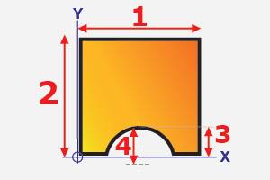
Pipe Support (Shape 26)
|
Parameters
1 - the total length or X-axis dimension from the shape origin.
2 - the total width or Y-axis dimension from the shape origin.
3 - the top of the notch/arc radius from the bottom of the shape or Y-axis dimension from the shape origin. This value should be less than or equal to the notch radius (P4).
4 - the arc radius of the notch or Y-axis dimension from the shape origin, which is automatically centered on the shape (P1).
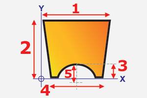
Slanted Pipe Support (Shape 27)
|
Parameters
1 - the total length or X-axis dimension from the shape origin.
2 - the total width or Y-axis dimension from the shape origin.
3 - the top of the notch/arc radius from the bottom of the shape or Y-axis dimension from the shape origin. This value should be less than or equal to the notch radius (P4).
4 - the length of the lower/notched side or X-axis dimension, which is automatically centered on the shape (P1).
5 - the arc radius of the notch or Y-axis dimension from the shape origin, which is automatically centered on the shape (P1).
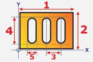
Slotted Plate (Shape 28)
|
Parameters
1 - the total length or X-axis dimension from the shape origin.
2 - the total width or Y-axis dimension from the shape origin.
3 - the distance between slots or X-axis dimension.
4 - the slot width or Y-axis dimension.
5 - the slot length or X-axis dimension.
Number of Slots - the number of slots in the plate.
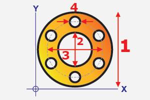
Round Flange (Shape 29)
|
Parameters
1 - the outer diameter.
2 - the inner diameter. This can be set to zero to remove the center hole.
3 - the diameter of the hole/bolt pattern.
4 - the diameter of each bolt hole.
Number of Bolts - the number of bolt holes in the flange.
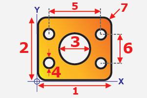
Rectangular 5 Hole Flange (Shape 30)
|
Parameters
1 - the total length or X-axis dimension from the shape origin.
2 - the total width or Y-axis dimension from the shape origin.
3 - the diameter of the center hole or X-axis dimension, which is automatically centered on the shape (P1). This can be set to zero to remove the center hole.
4 - the diameter of the four outer holes. This can be set to zero to remove the holes.
5 - the horizontal distance between the left and right bolt holes or X-axis dimension, which is automatically centered on the shape (P1).
6 - the vertical distance between the upper and lower holes or Y-axis dimension, which is automatically centered on the shape (P2).
7 - the corner radius of the flange.
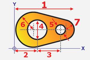
Cam Plate (Shape 31)
|
Parameters
1 - the total length or X-axis dimension from the shape origin.
2 - the left hole center or X-axis dimension from the shape origin.
3 - the distance between holes as an X-axis dimension.
4 - the diameter of the left hole, which is automatically centered on the shape vertically.
5 - the diameter of the right hole, which is automatically centered on the shape vertically.
6 - the outer radius of the left side of the plate.
7 - the outer radius of the right side of the plate.
Lollipop (Shape 32)
|
Parameters
1 - the distance from the center hole (or half of P3) to the right boundary of the shape as an X-axis dimension.
2 - the thickness or Y-axis dimension for the right side of the shape (tab).
3 - the total width or Y-axis dimension from the origin. This is the diameter of the left side of the shape.
4 - the center hole diameter, which is automatically centered in the diameter (or P3).
5 - the corner radius between the tab and the diameter (the transition radius).
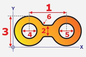
Chain Link (Shape 33)
|
Parameters
1 - the distance between holes as an X-axis dimension.
2 - the thickness of the tab (or transition) between the left and right halves.
3 - the total width or Y-axis dimension from the shape origin. This determines the outer diameter of the left and right sides.
4 - the diameter of the left inner hole. The value may be set to zero to remove the hole.
5 - the diameter of the right inner hole. The value may be set to zero to remove the hole.
6 - the corner radius of the tab between the left and right diameters (the transition radius).
Wedges (Shape 34)
|
Parameters
1 - the wedge length or X-axis dimension from the shape origin.
2 - the wedge width or Y-axis dimension from the shape origin.
3 - is the bevel width or Y-axis dimension applied to both wedges as a positive value. Setting this value to 0.00 creates both wedges with 90.00 degree sharp corners.
4 - the distance between the two wedges or the gap dimension. (Changing this dimension doesn't change the size of the wedges, but rather moves the upper wedge up in Y, so that it has the same dimensions as the lower wedge.)
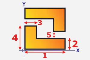
L Brackets (Shape 35)
|
Parameters
1 - the total length or X-axis dimension from the shape origin.
2 - the width or Y-axis dimension from the shape origin.
3 - the length or X-axis dimension from the shape origin.
4 - the total width or Y-axis dimension from the shape origin.
5 - the vertical distance or Y-axis dimension between brackets (the gap dimension).
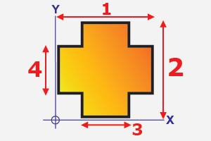
Cross (Shape 36)
|
Parameters
1 - the total length or X-axis dimension from the shape origin.
2 - the total width or Y-axis dimension from the shape origin.
3 - the length of the vertical section or X-axis dimension, which is automatically centered on the shape (P1).
4 - the width of the horizontal section or Y-axis dimension, which is automatically centered on the shape (P2).
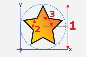
Star (Shape 37)
|
Parameters
1 - the diameter used to create the star. The outer points of the star meet this diameter.
2 - the angle range of the star corners.
3 - is the amount of rotation in degrees around the shape center. The rotation angle is applied counterclockwise from zero degrees (3 o'clock). With a value of zero, one of the corners points to zero degrees. A value of 90.00 degrees moves this corner to the 12 o'clock position.
Number of Corners - the number of corners for the star.
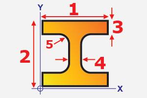
I Beam (Shape 38)
|
Parameters
1 - the total length or X-axis dimension from the shape origin.
2 - the total width or Y-axis dimension from the shape origin.
3 - the vertical width or Y-axis dimension of both horizontal sections.
4 - the horizontal length or X-axis dimension of the center section.
5 - the corner radius between the horizontal and vertical sections (the transition radius).
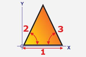
Angle Triangle (Shape 39)
|
Parameters
1 - the total length or X-axis dimension from the shape origin.
2 - the internal angle of the lower-left corner.
3 - the internal angle of the lower-right corner.
Lift Lug (Shape 40)
|
Parameters
1 - the total length or X-axis dimension from the shape origin.
2 - the total width or Y-axis dimension from the shape origin.
3 - the shoulder width or Y-axis dimension of the lower section.
4 - the length or X-axis dimension of the center section, which is automatically centered on the shape (P1).