


 The Shape Library
Introduction
This topic will explain the Shape Library functions, will explain whereto find the functions, and explain the options found in them.This topicwill also give a brief description of Dynamic Drawing, the Snap Incrementfunction, explain creation with quick steps, and provide links to relatedtopics.
The Shape Library Functions
Dynamic Drawing
This function supports Dynamic Drawing which allows you to use a combination of sketching and data entry to create the entities. After initially sketching the entity, it becomes an active entity, which is an entity that is in Modify Mode. Entities in Modify Mode display in the current Entity color, but displays with a greater line thickness to make them easier to identify. Active entities can be modified using data entry. The benefit of Dynamic Drawing is that you can quickly sketch a point to get the approximate result and then use data entry to update to the exact dimensions, and coordinate values as needed.
|
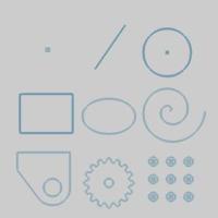
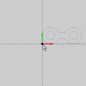
Entities in Modify Mode |
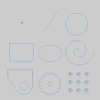
Final Entities |
|
|
In the images above, we see entities which are still in Modify Mode, followed by those same entities after they are finalized.
Snap Increment
This function support the use of the snap increment when selecting the location of the entities. The snap increment allows you to get precise results when using mouse selection and helps to reduce data entry modifications.
To learn more, view Snap Increment.
Navigation
To open the Shape Library:
- In the Shapes group, of the Create 2D ribbon, clickthe Shape Library icon.
The Data Entry Parameters
The Shape Library dialog in the Data Entry Manager displays the parametersfor one shape at a time.To choose a different shape, click on the diagramof the shape, and the choices will appear as shown in the image below.
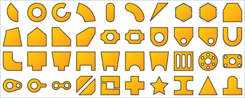
Click the shape that you want to create and appropriate parameters displayin the Data Entry Manager.
Shape Library Parameters
To learn about all shapes and their parameters, view ShapeLibrary Parameters.
Parameters
Dimensions
The available dimensions vary greatly from shape to shape.Each shapewill define the various size options by showing the corresponding numbersin its diagram .
Others
All of the Shape Library functions contain the Position and Orientationparameters as explained next.When creating shapes, it is often easiestto first define the parameters to get the proper shape before trying tomove, mirror, or rotate the shape as explained in this section.
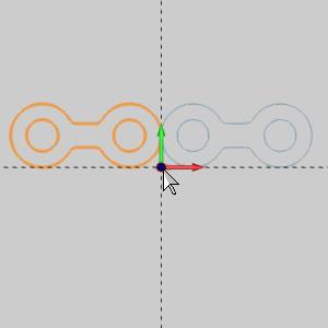
Note: When the Flip options are used, the shape isflipped around the origin.Referto the table below to see how the part behaves when flipping X, and Y,while using a bottom left origin option.
|
BottomLeft Origin and the Flip X, and Flip Y options |
||
|
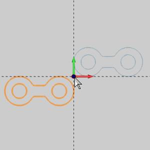
FlipX |
Flip X |
|
|
|
|
|
|
FlipX
|
Flip X
|
|
|
|
|
|
-
 - With this option selected the shape will be mirrored across theX-axis (XZ plane) at the origin of the shape.
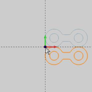
 - Flip Y
- With this option selected the shape will be mirrored across theY-axis (YZ plane) at the origin of the shape.
- Rotation Angle - is theamount of rotation in degrees around the Z-axis at the origin of theshape.
Origin
The origin allows you to define the location of the shape based on theorigin point.
- X - isthe X-axis location of the origin (or reference location) of the shape.
- Y - isthe Y-axis location of the origin (or reference location) of the shape.
- Z - isthe Z-axis location of the origin (or reference location) of the shape.
Choose the initial Origin location on thepart:
Center
Bottom Left
Bottom Center
Bottom Right
Right Center
Top Left
Top Center
Top Right
Left Center
View a Positionand Orientation Example.
Quick Steps - Shape Library
- After opening the ShapeLibrary, the parameters for the shape display in the Data Entry Manager andthe CAD preview shows the default shape in the graphics area.
In the Data Entry Manager, click the icon of the existing shape toview possible shapes. - Select the shape you want to create.
- Type all Dimensionvalues to define the dimensions of the shape.
The CAD preview of the shape updates in the graphics area.
Note: Whendefining the parameters for any shape, the CAD preview is removed wheninvalid values are entered.If you have entered all values for the shapeand the CAD preview isn't visible, confirm you have properly defined allthe parameters as shown in the Data Entry Manager diagram.
- Modify the values in the Otherssection of the Parametersgroup as needed to define the parts orientation.
- Set the location of the part by:
- Data Entry : Entervalues for X, Y, and Z into the Origin group.
- Sketch : Move yourmouse into the graphics area and set the shape by clicking ona snap point, or empty space.Keep in mind, the first click inthe graphics area will not finalize the part.Clicking a secondlocation however, will finalize the first.
- Combination: Usethe Sketch method, and then adjust the values in the Origin groupmanually.
Notice the order of the two previous steps,it is often easiest to define the shape dimensions and orientation first,and then set the position.
- In the DataEntry Manager, click OKto create the shape as shown in the CAD preview.
(You can click Cancelto exit the function and not create the shape.)
Note: ShapeLibrary entities are added to the CAD Tree which allows you to modifythe parameters of the shapes after creating them.