


 Text
Text
Introduction
This topic will explain the Text function, and the optionsfound in it.This topic will also describe where to find the function,provide quick steps and an example on how to use it, and provide links to related topics.
The Text Function
The Text function is designed to create alpha-numeric characters in the graphics area.
Snap Increment
This function support the use of the snap increment when selecting the location of the entities. The snap increment allows you to get precise results when using mouse selection and helps to reduce data entry modifications.
To learn more, view Snap Increment.
Navigation
To open Text:
-
In the Text group, of the Create 2D tab,click
 Text.
Text.
The parameters display in the Data Entry Manager.
The Data Entry Parameters
Font
- Font- Select a font type: WindowsFont or BobCADFont.
Tip: Open the BobCAD_AFNT_Text.bbcd file in your BobCAD-CAM Data/**Current Version**/Examples folder for a file with all possible BobCAD fonts already created in the graphics area.This will allow you to view each and choose the one that is right for you.
- Font List- Click the arrow to select the font from the list.
- Text box- Type the text that is placed in the graphics area.
Base Point
The Start point can be used to set the location of the bottom centerof the text.Another method of placement, is the sketch method.By hoveringover the text, and clicking once the text is highlighted, you can movethe text freely in the graphics area.Click again to place the text.Onceplaced, the Start Point coordinates can be adjusted to fine tune its placement.
- X - setsthe location along the X axis.
- Y - setsthe location along the Y axis.
- Z - setsthe location along the Z axis.
Bottom Center - This drop down will allow you to select the region of the text to be used for placement.
 Parameters
- Height - sets the maximumheight of the text.
- Ratio - for BobCAD fontsonly, this sets the X:Y size ratio of the text.
- Angle - type an angle value,from the positive X-axis, at which the text is placed.
- Slant - for BobCAD fontsonly, this adds a slant to each character.
- Ext.Spacing - definesan extra distance that is added between each character.
- Vectorize
- On - With thistoggle on, each character is created as multiple entities.Theaccuracy value becomes available as the text field next to theVectorize button.
- Off - With thistoggle off, each character is created as a single entity.
Style
- B - creates thetext with boldformatting.
- I - createsthe text with italicformatting.
-
 - When multiplelines of text are being created, this option will align the text tothe left.
 -
 - When multiplelines of text are being created, this option will align the text tocenter.
 -
 - When multiplelines of text are being created, this option will align the text tothe right.
- OK - finalizes the function.
- Cancel - exits the function.
Quick Steps - Text
- Open the function.
- Enter text into the text box.
The text preview appears as text is added. - Alter the font, parameters, and style as needed.
- When the text has the desired look, move the text by:
- Choose the Base Point region in the drop down list, then either:
- Enter the Base Point values manually.
- Click on the Base Point Sphere in the graphics area, move text, and click again to set location.
- Combination of 1 & 2.
- Enter the Base Point values manually.
- Choose the Base Point region in the drop down list, then either:
- Repeat as necessary.
- Click Cancel to exit function.
Example
1) Creating a Point
- In a new file, click on the
 Point icon in the Create2D ribbon.
 - With the default Creation Option selected, enter the following valuesin the Coordinate group:
- X: 1.0000
- Y: 1.0000
- Z: 0.0000
- Click OK.
A point is created.While this point is not necessary for text creation,we will use it as a position we wish to move the text to.
2) Creating the Text
- Click on the
 Texticon in the Create 2D ribbon.
The Data Entry Manager is populatedwith fields for user input. - In the Data Entry Manager:
- With the Windowsfont highlighted, select TimesNew Roman in the Fontfield.
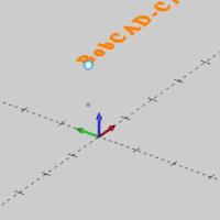
- In the Textfield, type in "BobCAD-CAM".
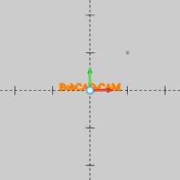
The preview updates as the text is typed out.
- Input 0.375 forthe Text Height.
- In Extra Spacinginput 0.125.
- Hover over the sphere at the bottom center of the text.
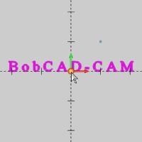
Notice the text highlights when the you move your mouse over it. - Click the sphere.
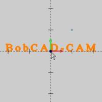
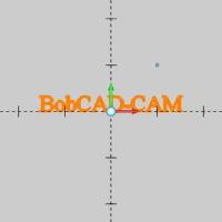
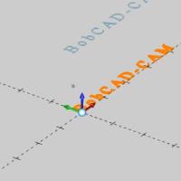
Notice the sphere disappears, and the text is no longer highlighted when you click it.The textis now free to be moved manually. - Move your pointer to the point we created earlier.
With the point highlighted, clickit.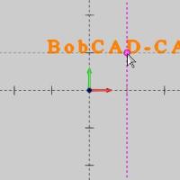
The text is locked to the location we have just clicked.
Note: Although we could have just entered this location rather than using a point, this is to demonstrate if there was an entity, whose location we were not familiar with which we needed to snap the text to, we could.
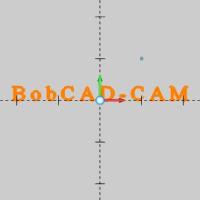
- Move to an ISO 7 viewby pressing Ctrl+7 on yourkeyboard.
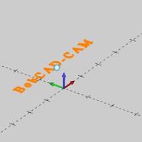
- In the Base Point group of the Data Entry Manager, click the down arrow for Bottom Center, and select Bottom Left.

Notice the text is shifted so that the Base Point now represents the bottom left of the text instead of the bottom center of the text. - In the Data Entry Manager,enter 1.0000 into the Z text field, andpress Enter.
The text is moved in Z. - Click OK.
The text is created, and the Base Point values are reset.The previewshows the default position. - To end this function, click Cancelin the Data Entry Manager.

That concludes this example.
Related Topics
Examples of BobCAD AFNT Fonts
While the available Windows font will vary greatly based on what the individual has installed on their computer, the BobCAD Fonts installed for every user.Below is a list of all BobCAD Fonts, with their name on the left, and example on the right.Hover over a font example to see an enlarged image of it.
Tip: You can also access a BobCAD-CAM file with all fonts on a separate layer in your examples folder: C:\BobCAD-CAM Data\**Current Version**\Examples\BobCAD_AFNT_Text.bbcd
| AFNT01 | 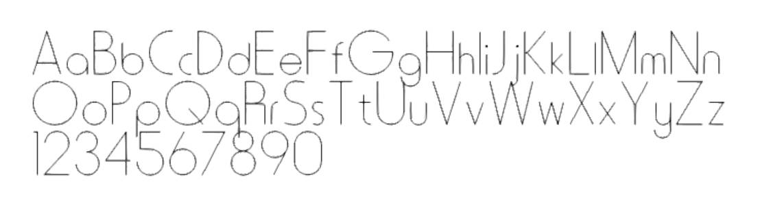
|
| AFNT02 | 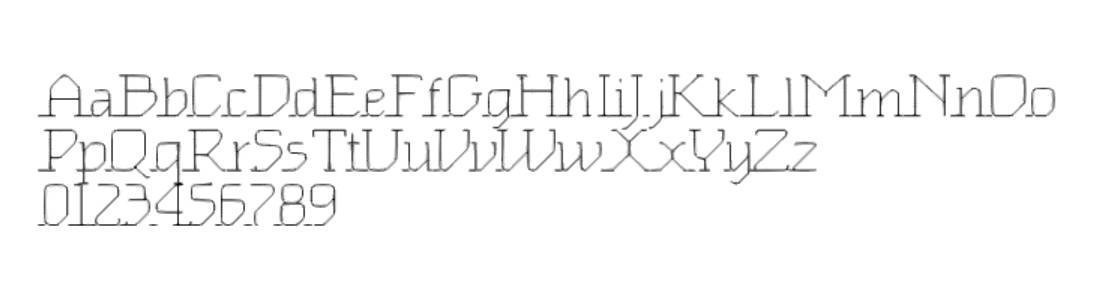
|
| AFNT03 | 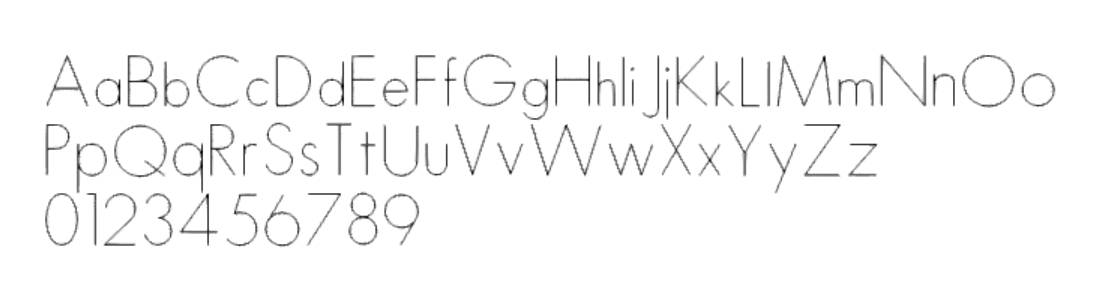
|
| AFNT04 | 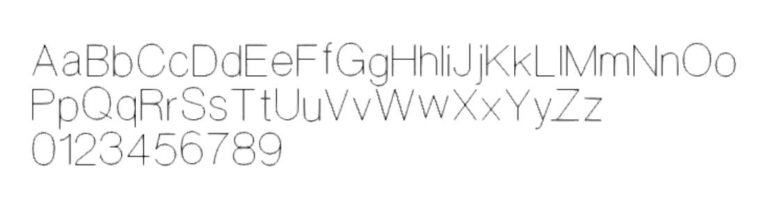
|
| AFNT05 | 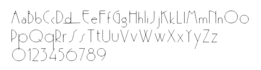
|
| AFNT06 | 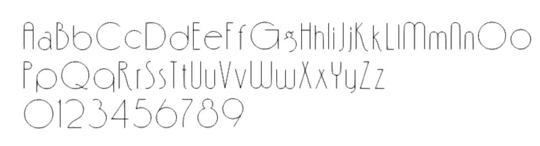
|
| AFNT07 | 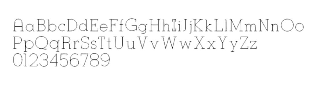
|
| AFNT08 | 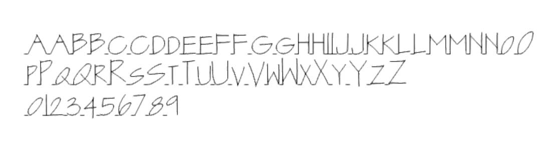
|
| AFNT09 | 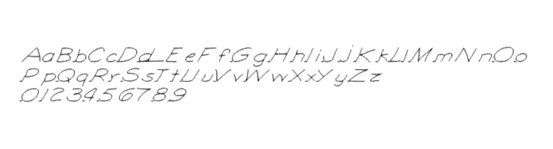
|
| AFNT10 | 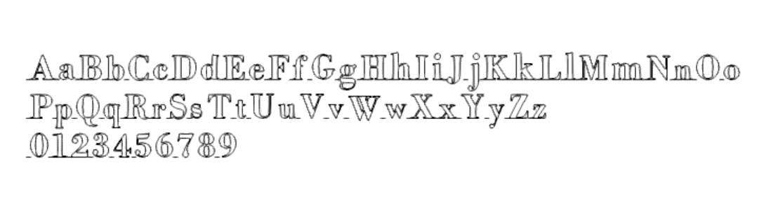
|
| AFNT11 | 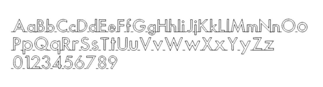
|
| AFNT12 | 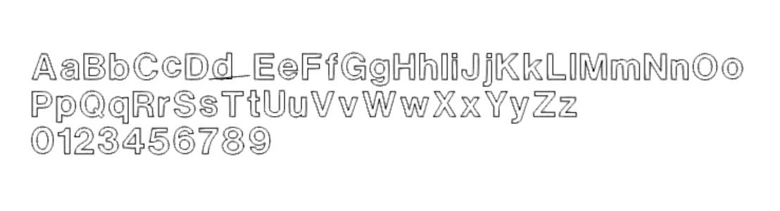
|
| AFNT13 | 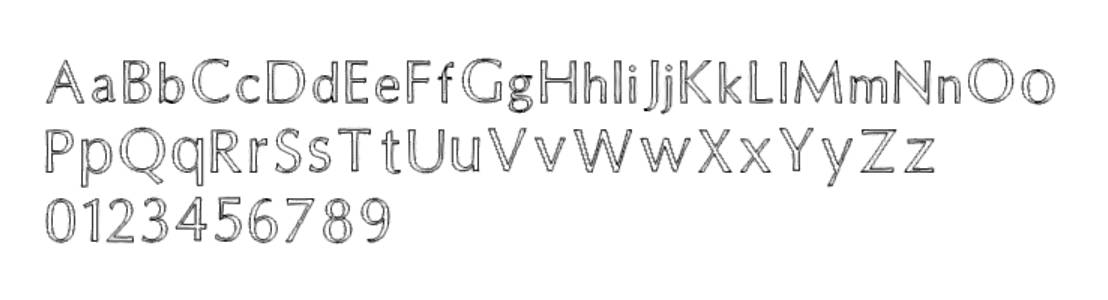
|
| AFNT14 | 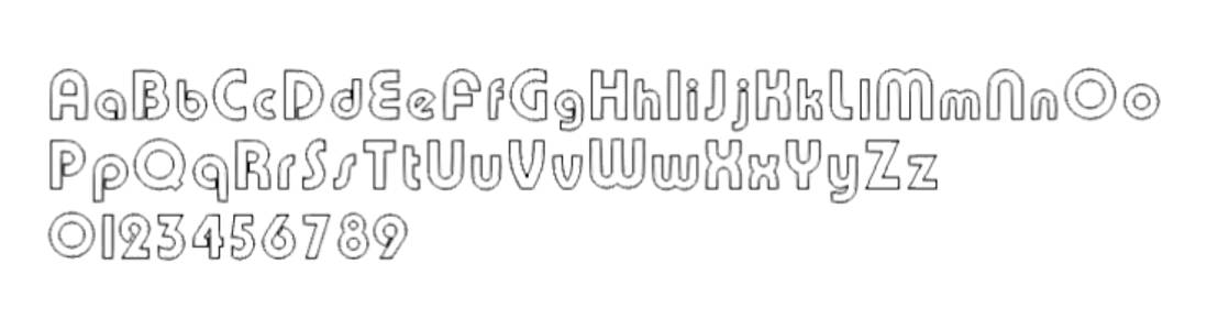
|
| AFNT15 | 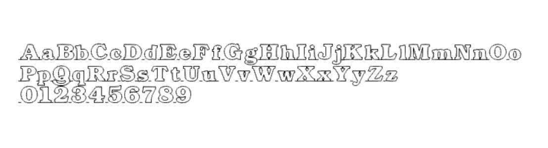
|
| AFNT16 | 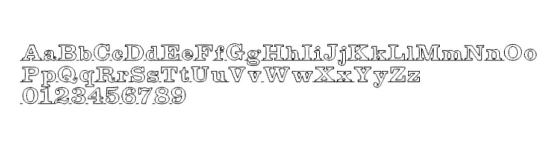
|
| AFNT17 | 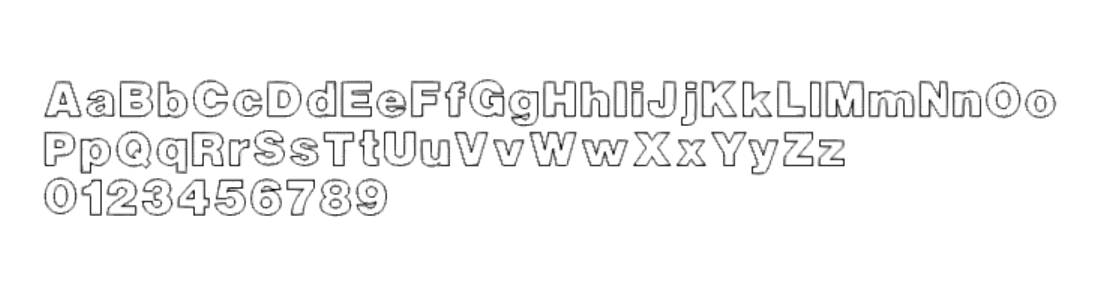
|
| AFNT18 | 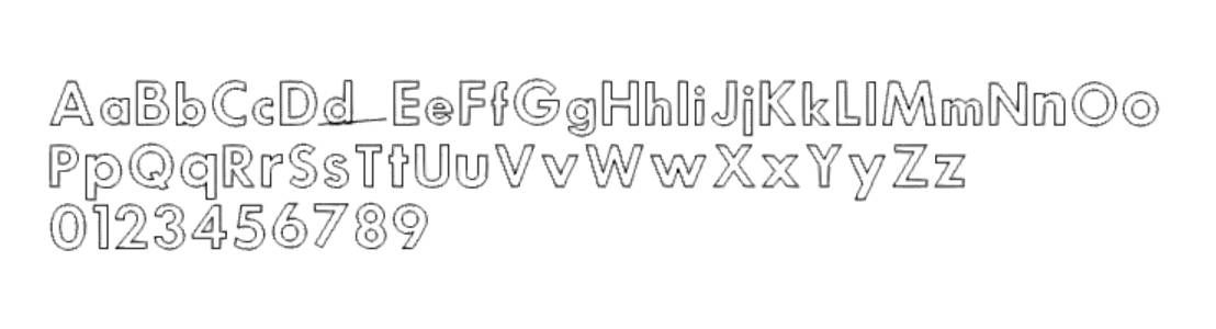
|
| AFNT19 | 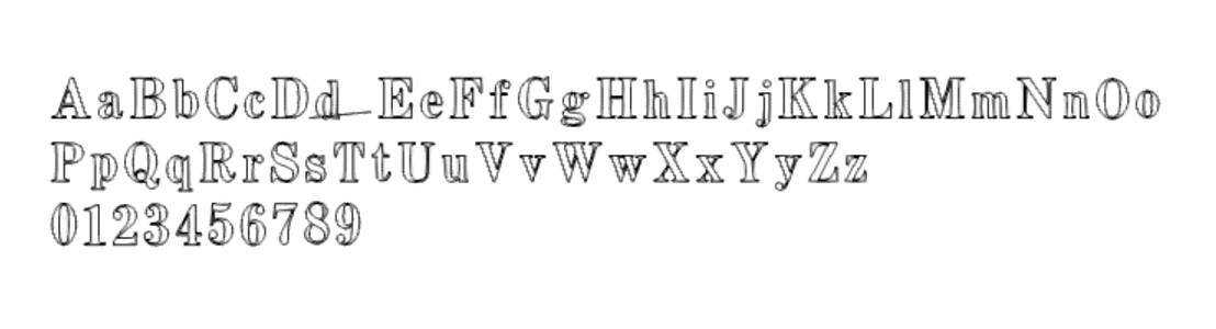
|
| AFNT20 | 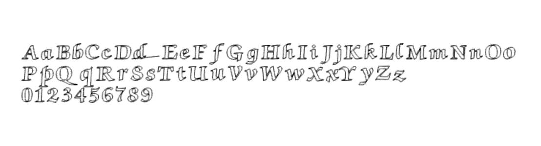
|
| AFNT21 | 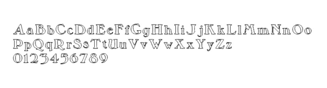
|
| AFNT22 | 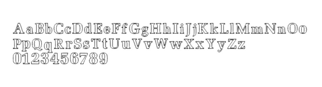
|
| AFNT23 | 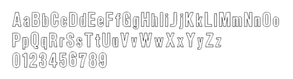
|
| AFNT24 | 
|
| AFNT25 | 
|
| AFNT26 | 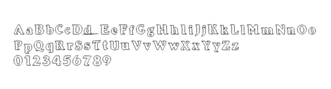
|
| AFNT27 | 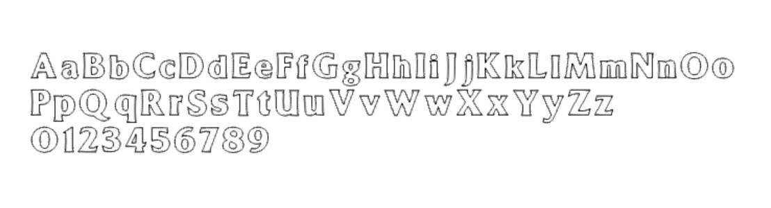
|
| AFNT28 | 
|
| AFNT29 | 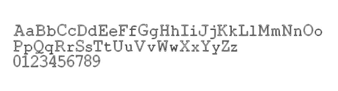
|
| AFNT30 | 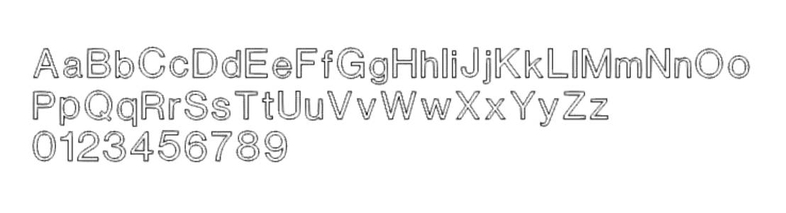
|
| AFNT31 | 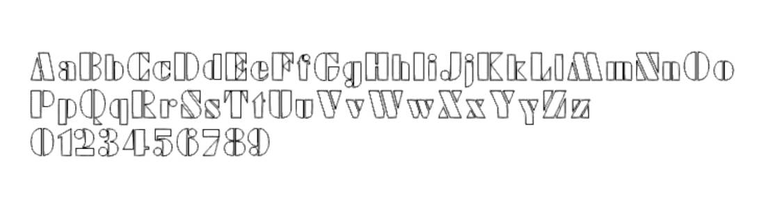
|
| AFNT32 | 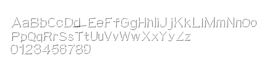
|
| AFNT33 | 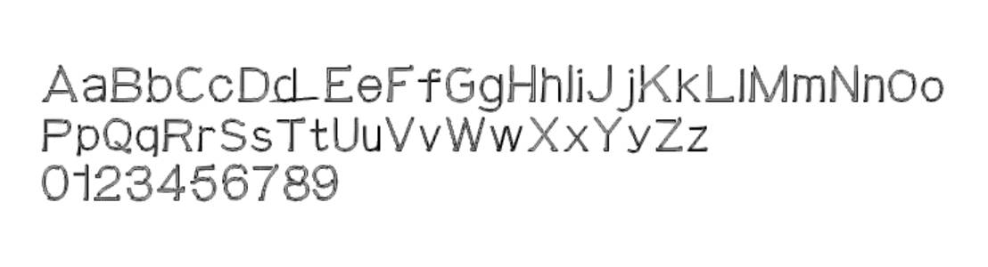
|
| AFNT34 | 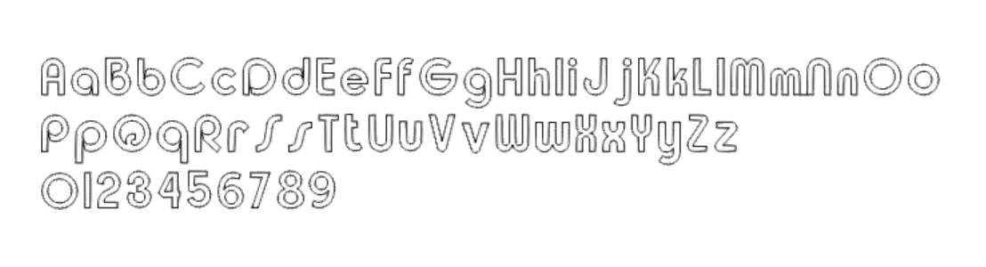
|
| AFNT35 | 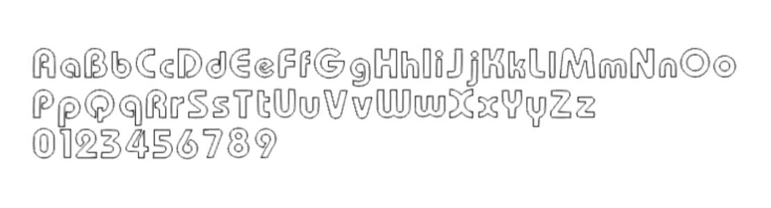
|
| AFNT36 | 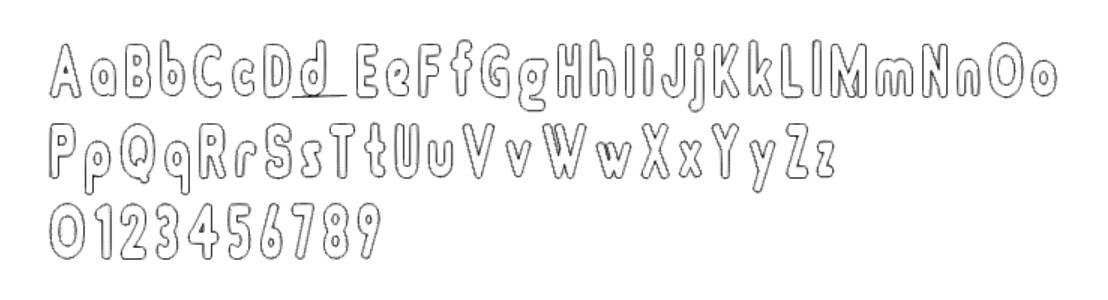
|
| AFNT37 | 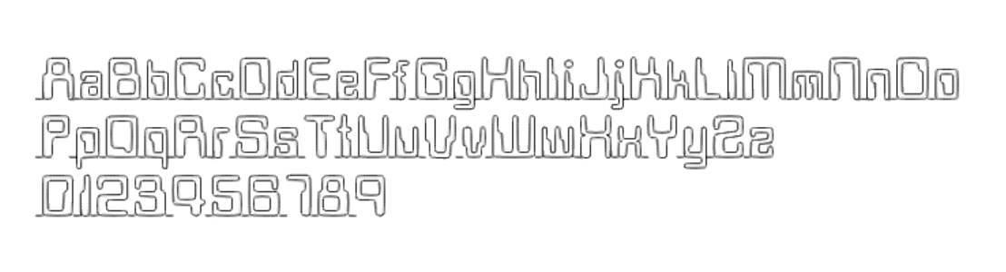
|
| AFNT38 | 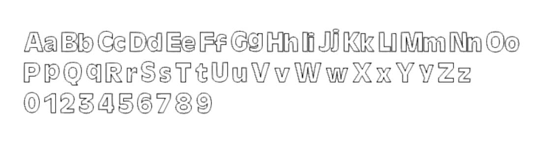
|
| AFNT39 | 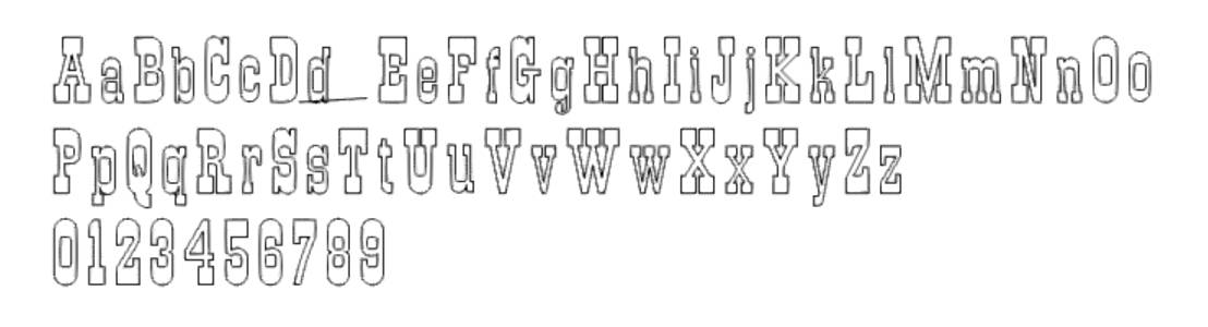
|
| AFNT40 | 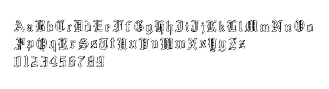
|
| AFNT41 | 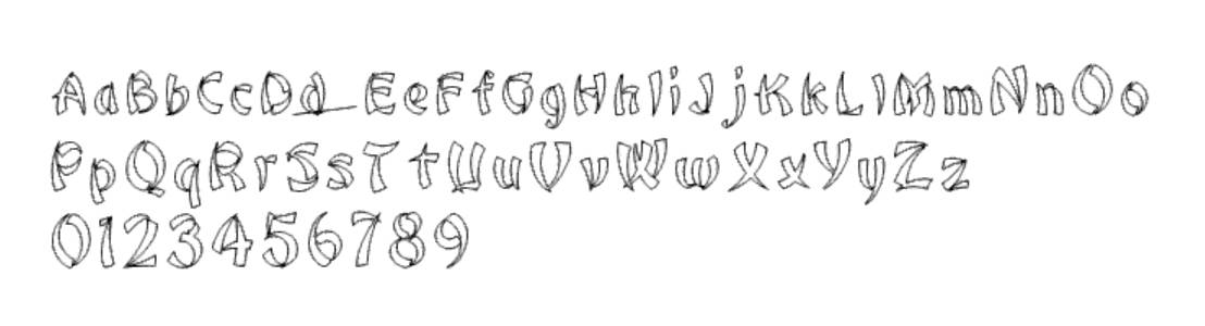
|
| AFNT42 | 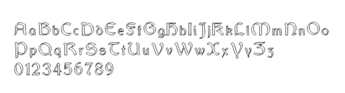
|
| AFNT43 | 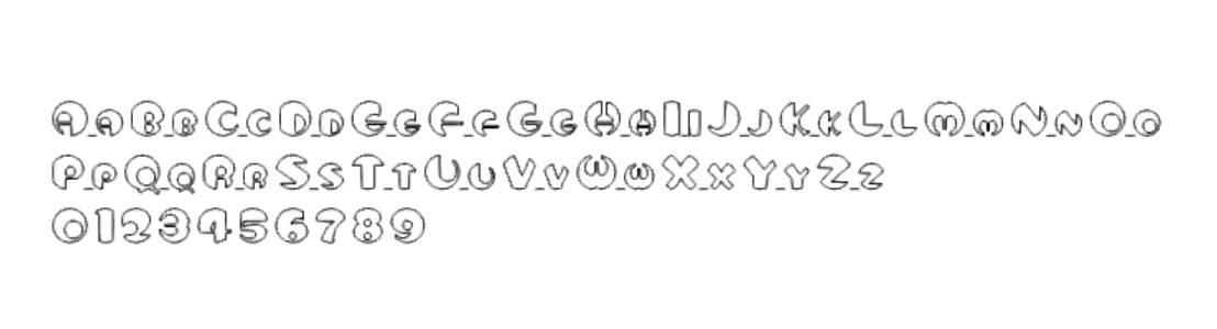
|
| AFNT44 | 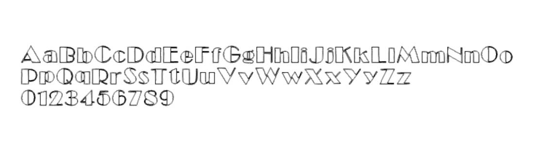
|
| AFNT45 | 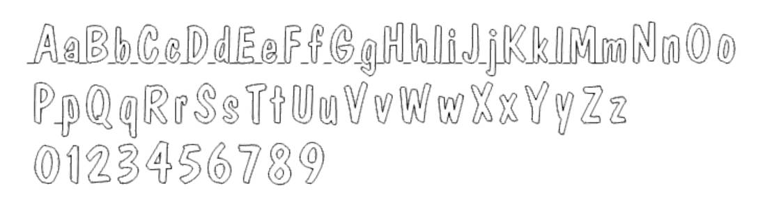
|
| AFNT46 | 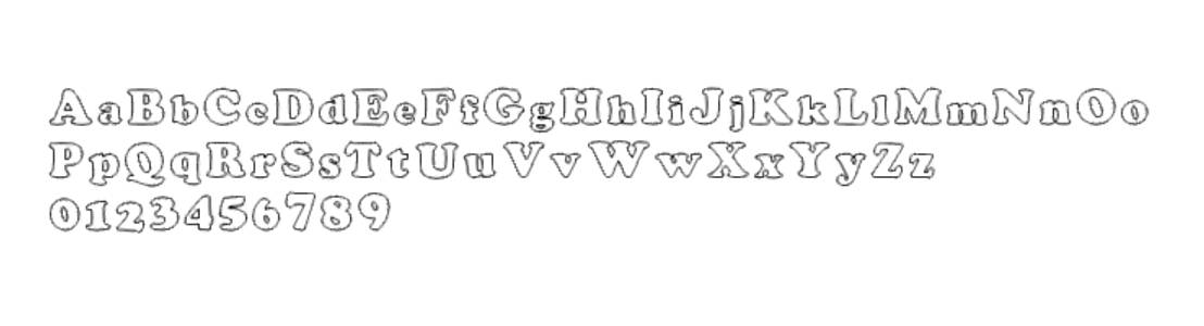
|
| AFNT47 | 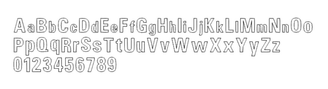
|
| AFNT48 | 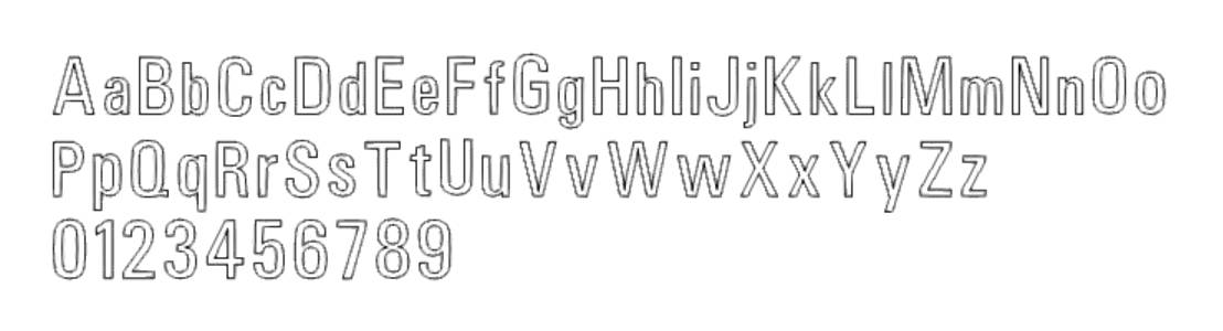
|
| AFNT49 | 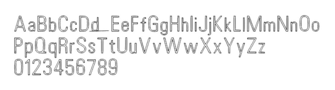
|
| AFNT50 | 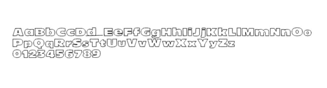
|
| BobCAD Default | 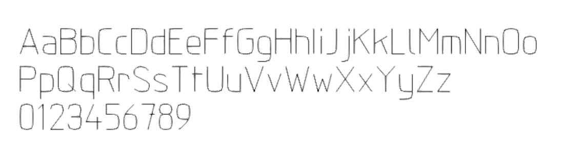
|
| Box | 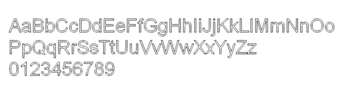
|
| English | 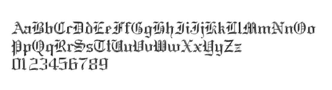
|
| Gothic | 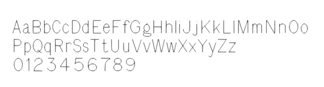
|
| Helv | 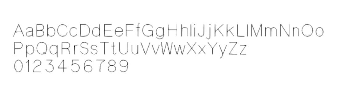
|
| Roman | 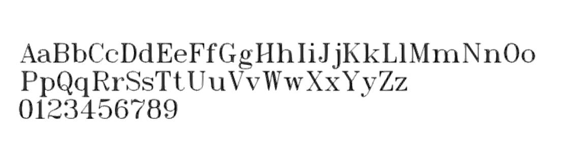
|
| Spec | 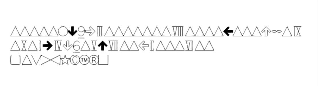
|
| Stamp | 
|