


Create 3D: Dynamic Drawing
Introduction
This topic explains how to use Dynamic Drawing with solids in BobCAD-CAM.
Dynamic Drawing
Dynamic Drawing provides the ability to modify the location and dimensionsof solid entities using sketch handles, data entry, or a combination ofboth.
Applies To
|
Primitives |
Extrude |
Surface Modify |
|
Sphere |
Extrude Boss |
Extend Surface |
|
Cube |
Extrude Cut |
|
|
Cone |
Extrude Curve |
|
|
Cylinder |
Extrude Surface |
|
|
Torus |
Imprint |
|
Sketch Handles
There are two main types of sketch handles: origin and dimension.
Snap Increment
Dynamic drawing supports the use of the snap increment when using sketchhandles to set the origin location or dimension values.The snap incrementallows you to get precise results when using mouse selection and helpsto reduce data entry modifications.
To learn more, view Snap Increment.
Origin
A small sphere displays at the origin of the entity.This sketch handlecontrols the origin location of the entity.

Dimensions
Arrows display for each dimension that can be modified.These includelength, width, height, and radius dimensions as well as the distancesfor extrusion functions.


How to Use Sketch Handles
-
Click to select the handle and activate sketching.
This allows you to modify the location orone of the dimensions of the entity.Note that the snap increment appliesto the available snap locations for these values.
Important: Whenselecting dimension sketch handles, you must click the small cone at theend of the handle to select it.
-
Move the mouse pointer to a new location.
The location or dimension of the entity updates graphically (with awireframe display) as you move the sketch handle. -
Click to anchor the sketch handle.
The location and dimension parameters updateand can now be modified using data entry.
Modify the Origin Sketch Handle Example
The following image shows the CAD preview entity for a cylinder thatis moved.

-
Point to the origin sphere so that it displaysin the Highlight color.

-
While it displays in the Highlight color,click the origin sphere to enable sketching and move it to a new location.

Note: Whilemoving the origin, the CAD preview remains in the previous location, andthe shape displays using a wireframe preview and the sketch handles asshown.
-
Click to anchor the entity at the new location and update theCAD preview.


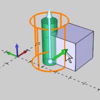
You can click a point, snap point, or anywhere in the Workspace toplace the origin.In the example, the snap point of a cube is usedto place the origin. -
After moving the origin, you can now type XYZvalues in the Data Entry Manager to update the origin as needed.
Modify Dimension Sketch Handles
The same process as explained in the previous example can be appliedto the dimension sketch handles as well.
-
Click the arrow (small cone) of the dimensionhandle to enable sketching.

Important: When selectinga dimension sketch handle, click the small cone at the end, not the cylindricalportion, of the handle.
-
You can then move the pointer in either direction to modifythe selected dimension.


-
Click to anchor the sketch handle.

-
You can modify the sketch handles of the other dimensions aswell.
The previous images show modifying the cylinder height and the followingimages show modifying the cylinder radius.

-
Before finishing the cylinder, the Data Entry parameters canbe modified to update the current dimensions.
For the current example, the Radius is modified in the Data Entry Manager.
-
Now that the desired location and dimensions are defined, clickOK to create the cylinderas shown in the CAD preview.

Notice in the previous image that the sketch handles still displayafter creating the cylinder.This is the CAD preview for the nextcylinder as the Cylinder function is still open in the Data EntryManager.
You can see this by turning on transparency as shown next.
-
To finish the dynamic drawing and close the Data Entry Manager,click Cancel.

The information provided in this examplecan be applied to the other Dynamic Drawing functions listed at the topof this document.Be sure to view the snapincrement topic to learn about how it applies to using sketch handles.
This concludes the example.