


 Extrude Curve
Introduction
This topic will explain the Extrude Curve function, will explain whereto find the function, and explain the options found in it.This topicwill also give a brief description of Dynamic Drawing, the Snap Incrementfunction, explain creation with quick steps and examples, and provide links to relatedtopics.
The Extrude Curve Function
The Extrude Curve function creates a solid or surface shell by extrudingopen or closed wireframe curves to a specified distance.
Tip: This functiondoes not merge with other solids in the Workspace.To extrude and mergewith other solids, use Extrude Boss.

Dynamic Drawing
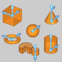
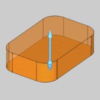
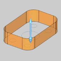
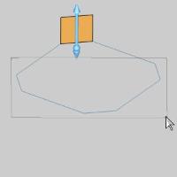
This function supports Dynamic Drawing which allows you to use a combination of sketching and data entry to create the entities. Prior to confirming the desired result in the function, an adjustable preview is visible. These previews can be modified using the sketch handles, data entry, or a combination of both. The benefit of Dynamic Drawing is that you can quickly place and adjust the size to get the approximate result, and then use data entry to update to the exact dimensions, and coordinate values as needed.
|
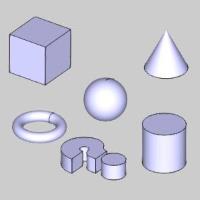
Preview with Sketch Handles |
Final Entities |
|
|
In the images above, we see the preview of entities which can be adjust with sketch handles, followed by those same entities after they are finalized.
Snap Increment
This function support the use of the snap increment when selecting the location of the entities. The snap increment allows you to get precise results when using mouse selection and helps to reduce data entry modifications.
To learn more, view Snap Increment.
Navigation
To open the Extrude Curve:
-
In the Extrude group, of the Create 3D ribbon,click
 Extrude Curve.
The Extrude Curve parameters display in the DataEntry Manager.
The Data Entry Parameters
Selected Geometry
|
|
|
| The list will display all entities currently selected for the function. | |
 (Delete All)
- removes all entities from the Selected Geometry list.
(Delete All)
- removes all entities from the Selected Geometry list.Positive Direction
- Distance - sets the distanceof the extrusion from the selected geometry in the positive direction.You can use dynamic sketch handles or data entry to set this value.The snap increment appliesto the distance value when using sketch handles.
|
Distance Along Z-AxisWhe |
Distance Along Normal |
|

|
-
DraftAngle - creates an angle along the edge of the extruded shapein the positive direction.This also applies to any internal shapeswhen you select more than one curve to extrude.This can be a positiveor negative value.
Draft Along Z-Axis
Draft Along Normal

Other Direction
- Distance - sets the distanceof the extrusion from the selected geometry in the negative direction.You can use dynamic sketch handles or data entry to set this value.The snap increment appliesto the distance value when using sketch handles.
-
DraftAngle - creates an angle along the edge of the extruded shapein the negative direction.This also applies to any internal shapeswhen you select more than one curve to extrude.This can be a positiveor negative value.
Options
- With Caps
![]() - Extrudes the wireframe geometry and adds a surface to the top and bottom.All surfaces are stitched into a solid
- Extrudes the wireframe geometry and adds a surface to the top and bottom.All surfaces are stitched into a solid
![]() - Extrudes the wireframe geometry without adding a surface to the top and bottom.
- Extrudes the wireframe geometry without adding a surface to the top and bottom.
|
|
|
|
|
|
-
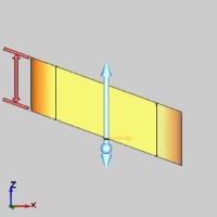
 AlongNormal - the extrusion occurs parallel to the normal directionof the plane created by the selected curve.
FrontView 
TopView
-
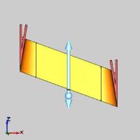
 AlongZ-Axis - the extrusion direction is the Z-axis regardless ofhow the selected curve is oriented.
FrontView 
TopView
- OK - finalizes the function.
- Cancel - exits the function.
Quick Steps - Extrude Curve
- Open the function.
The Selected Geometry list automatically has focus. - Select the geometry to extrude.
The geometry is added to the Selected Geometry.
Note: The geometry can be closed wireframe chains, surface edges, or planarsurface geometry.When using a surface, the software automaticallyextracts the edges of the surface to use for the boss.
Tip: Selection can sometimes be made easier by pressing Sto turn off the shaded view of solids.
- Update the parameters to achieve the desired result, which is visible in the preview.
- Click OK to confirm.
The feature is added to the CAD Tree. - Repeat as necessary.
- Click Cancel to close the function.
Examples
Example 1 (Single Curve)
Note: Inthe images below, both the Show Axis X-Y and Show Gnomontoggles have been disabled in the Axis X-Y group of the SettingsPart > Display dialog.
- In the Quick Access Toolbar, click
 New.
New. - Click anywhere in the graphics area, to give it focus,and press Ctrl+7 to selectthe ISO 2 view.
- In the Shapes group, of the Create 2D ribbon,click
 Rectangle.
The Rectangle parameters display in the Data Entry Manager and the Preview appears showing the default values.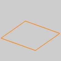
- In the Corner Type group, click
 to create chamfered corners.
The preview updates.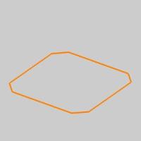
- Input 0.3750for the Chamfer Length.
The Preview updates.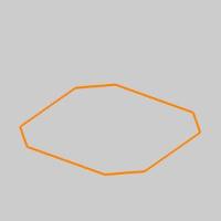
- In the Base Pointgroup, change the Z valueto 0.5000.
The Preview updates.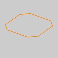
- To create the rectangle as shown in the CAD preview,click OK.
The rectangle is created in the graphics area.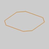
- In the Extrude group, of the Create 3D ribbon,click Extrude Curve.
The Extrude Curve parameters display in the Data Entry Manager.
Select the entity shown in the image below.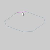
The entity is added to the Selected Geometry list and the Preview updates.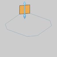
- Window pick the remainder of the entities, as shownin the image below.
The entities are added to the Selected Geometry list and the Previewupdates.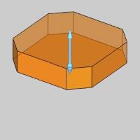
- To create the geometry as shown in the CAD preview,click OK.
The Extrude Surface is created in the graphics area, and an Extrude Curve feature isadded to the CAD Tree.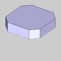
Tip: With Caps and AlongNormal are selected by default.This adds a top and bottom surfaceto the extruded geometry to create closed geometry instead of creatinga surface shell (With Caps off).Because the normal of the plane createdby the curve is the same as the Z-axis, Along Normal and Along Z-Axiscreate the same result for this example.
-
To end the function, click Cancel.
This completes Example 1.Leave the fileopen and continue to Example 2 to learn more about Extrude Curve.
Example 2 (Multiple Curves with Draft Angle)
-
After completing Example 1, press Ctrl+Zto undo the extruded geometry.
The Extrude Curve is undone and the rectangle remains.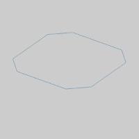
-
In the Entity group, of the Create 2D ribbon, click the down arrow under
 Arc, and select
  Arc Center.
The Arc Coordinate parameters display in the Data Entry Manager and the Preview appears showing the defaultvalues.
-
In the Data Entry Manager, in the CenterZ box, type 0.500.Press Tab.
The Preview updates.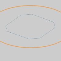
-
In the Dimensions group, change the Radius value to0.3750 and press Tab.
The Preview updates.
-
To create the arc as shown in the CAD preview,click OK.
The Arc is created in the graphics area.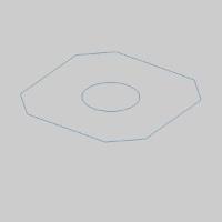
-
In the Extrude group, of the Create 3D ribbon,click
Extrude Curve.
The Extrude Curve parameters display in the Data Entry Manager. -
Window pick the geometry, as seen in theimage below.
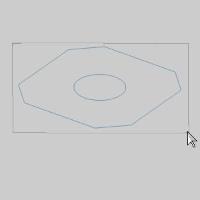
The entities are added to the Selected Geometry list and the Previewupdates.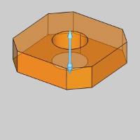
Tip: When selecting geometry for a function like this, if each chain must be selected one at a time, select the inner geometry first, so the preview does not obstruct the view of other geometry which may need to be selected for the function.
-
In the PositiveDirection group, change the Distancevalue to 0.000.
The Other Direction group isautomatically given a default value of 1.0000,and the Preview Updates.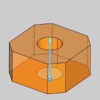
-
In the OtherDirection group, change the Distancevalue to 0.5000.
The Preview updates.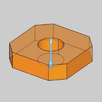
-
In the DraftAngle box, type 5.000.
The Preview updates.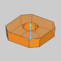
Note: You canuse negative values to invert the Draft Angle.
-
To create the geometry as shown in the CAD preview, click OK.
The Extrude Surface is created in the graphics area, and an Extrude Curve feature isadded to the  CAD Tree.
-
To end the function, click Cancel.
That concludes these examples.