


 Imprint
Introduction
This topic will explain the Imprint function, will explain whereto find the function, and explain the options found in it.This topicwill also give a brief description of Dynamic Drawing, the Snap Incrementfunction, explain creation with quick steps and an example, and provide links to relatedtopics.
The Imprint Function
The Imprint function is designed to extrude a curve, and subtract anexisting CAD model from that extrusion, while keeping the original modeland the newly created imprint.

Dynamic Drawing
This function supports Dynamic Drawing which allows you to use a combination of sketching and data entry to create the entities. Prior to confirming the desired result in the function, an adjustable preview is visible. These previews can be modified using the sketch handles, data entry, or a combination of both. The benefit of Dynamic Drawing is that you can quickly place and adjust the size to get the approximate result, and then use data entry to update to the exact dimensions, and coordinate values as needed.
|
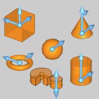
Preview with Sketch Handles |
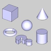
Final Entities |
|
|
In the images above, we see the preview of entities which can be adjust with sketch handles, followed by those same entities after they are finalized.
Snap Increment
This function support the use of the snap increment when selecting the location of the entities. The snap increment allows you to get precise results when using mouse selection and helps to reduce data entry modifications.
To learn more, view Snap Increment.
Navigation
To open Imprint:
- In the Extrude group, of the Create 3D tab, click
 Imprint.
The parameters display in theData Entry Manager.
The Data Entry Parameters
|
Imprint |
|
|
|
|
| The Imprint list shows all selected entities to use as the profile of the imprint. | |
 (Delete All)
- removes all entities from the Selected Geometry list.
(Delete All)
- removes all entities from the Selected Geometry list.|
Selected Solids |
|
|
|
|
| The Selected Solids list shows all selected entitiesto create an imprint of. | |
Distance
This group defines how far the imprint is extruded prior to being subtractedfrom the selected solids.
![]() DefaultDistance- extrudes the Profile Chains through the entirety of the SelectedSolids, unless a specific distance is entered.
DefaultDistance- extrudes the Profile Chains through the entirety of the SelectedSolids, unless a specific distance is entered.
![]() Pick a Point - allows you to picka point / snap point to extrude the imprint to.
Pick a Point - allows you to picka point / snap point to extrude the imprint to.
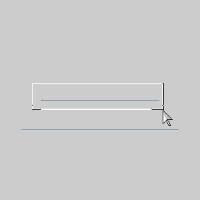
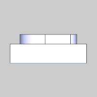
![]() End Surface - allows you to picka surface to extrude to.The selected surface also acts as a Split Surfaceon the extrusion, as seen in the animation below.
End Surface - allows you to picka surface to extrude to.The selected surface also acts as a Split Surfaceon the extrusion, as seen in the animation below.
Important: Important : When using the End Surface option,the selected surface should be larger than the Profile Chains selectedto be the imprints.
![]() Along Normal- extrudes the Profile Chains along the normal of the Profile Chains.
Along Normal- extrudes the Profile Chains along the normal of the Profile Chains.
![]() Along Z-Axis - extrudes the ProfileChains along the Z direction of the current UCS.
Along Z-Axis - extrudes the ProfileChains along the Z direction of the current UCS.
- OK - performs the functionto create the geometry shown in the CAD preview.
- Cancel - closes the DataEntry Manager.
Quick Steps - Imprint
To create an imprint, there are only a few key steps to follow:
-
Select the ProfileChains.
These are the entities that will be extruded to make the imprint.
By default, the Profile Chains has focus and is ready to have ProfileChains added. -
Click in the SelectedSolids list to put focus on it.
-
Select the SelectedSolids.
These are the solids the imprint is to be made from.
With a solid selected, the preview is displayed. -
Set the Distance.
This is how much to extrude from the Profile Chains. -
To confirm the Imprint, click
 (OK), or press Spacebar.
The feature is added to the CAD Tree. -
Click Cancelto close the function.
Example
Thisexample will have you:
- Create Two Rectangles
- Create a Cam Plate Layer
- Create the Cam Plate
- Extrude the Cam Plate
- Create a Soft Jaws Layer
- Create the Imprint
- View the Result
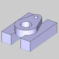
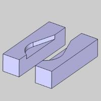
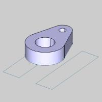
Intended result:
Part 1) Create Two Rectangles
For this example, we will be imprinting two rectangles that will becomea set of soft jaws to hold our Cam Plate.Our first step will be to createthose rectangles.
-
In the Shapes group, of the Create 2D ribbon,click
 Rectangle.
The preview with default settings displays.
-
Set the Length(X) to 4.000.
The preview updates.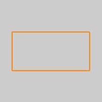
-
Set the Width(Y) to 1.000.
The preview updates.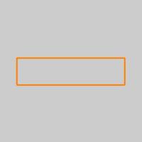
-
In the Origingroup, set the Z value to-0.75.
The Preview updates. -
Click OKto confirm the settings and placement of the first rectangle.
The first rectangle is created.
-
In the Origingroup, set the Y value to2.0000.
The Preview updates.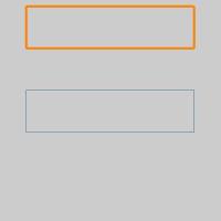
-
Click OKto confirm the settings and placement of the second rectangle.
The second rectangle is created.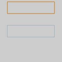
-
Click Cancelto exit the Rectangle function.

Part 2) Create a Cam Plate Layer
In order to keep our geometry organized, we will create a new CAD layer,so that we may easily hide and show different aspects of our file.
-
Right-click in the LayersManager and select Add NewLayer.
A layer iscreated and the name is highlighted to allow for alteration. -
Type "Solid"as the name for the new layer and press Enter,or click off of the layer to set the name.
-
Right-click the new Solid layer and select Active Layer to setthat as the active layer.
The Solid layer is now marked as active.
Part 3) Create the Cam Plate
Next, we will create the Cam Plate that will be extruded into the solidwill create an imprint from.
-
In the Shapes group, of the Create 2D ribbon, clickthe
 Shape Library icon.
The Disk shape populates in the Data Entry Manager. - Click the image of the disk shape to launch the shape library dialog.
The Shape Library dialog appears. -
Select the
 icon.
icon.
The parameters open in the Data Entry manager, and the Preview displays.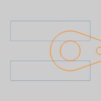
-
In the Positionand Orientation group, change the Xvalue to -1.5000.
The Preview updates.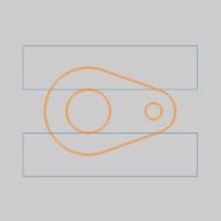
-
Click OKto confirm the settings and placement of the Cam Plate.
The Cam Plate is created in the graphics area, and the Cam Plate featureis added to the CAD Tree.
Part 4) Extrude the Cam Plate
The next step is to create the extrusion of the Cam Plate.
-
In the Extrude group, of the Create 3D ribbon,click
 Extrude Curve.
 -
Press Ctrl+2 to get into a Front view.
The View updates.
-
Window pick the Cam Plate.
The Preview appears, showing the default settings.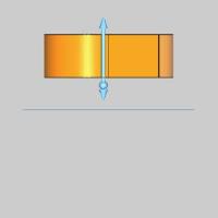
-
Change the PositiveDirection value, from 1.000 to 0.7500.
The preview updates.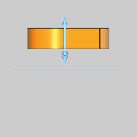
-
Click OKto confirm the settings and placement of the Cam Plate.
The Solid is created and an Extrude Curve feature is addedto the CAD Tree.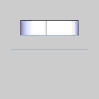
Although our geometry is shown in an isometric view, we will remain,or return to, a side view in order to make selection easier.
Part 5) Create a Soft Jaws Layer
We will create a new CAD layer to keep our imprint separate from therest of the geometry.
-
Right-click in the Layers Manager and select Add NewLayer.
A layer iscreated and the name is highlighted to allow for alteration. -
Type "SoftJaws" as the name for the new layer and press Enter,or click off of the layer to set the name.
-
Right-clickthe new Soft Jaws layer, and select Active Layer toset that as the active layer.
The Soft Jaws layer is now marked as active.
Part 6) Create the Imprint
Now that we have a solid model, we can create an imprint of it.
-
In the Extrude group, of the Create 3D tab, click
Imprint. -
By default, the Profile Chains group hasfocus and is ready to accept the geometry we select.
Window pick the Soft Jaws geometry as seen in the image below.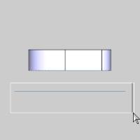
The geometry highlights, and the entities are added to the ProfileChains list.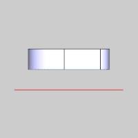
-
Click in the SelectedSolids list to allow us to add our solid to the list.
-
In the graphics area, hover over the solidto highlight it.
The solid highlights.
-
Click the solid to select it and add it tothe Selected Solids list.
The Preview appears.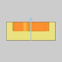
-
In the Distancegroup, change the option from Default, to the Distanceoption.
-
Change the Distancevalue to 1.0000.
The Preview updates.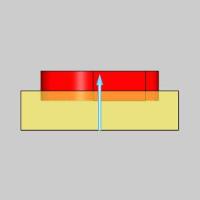
-
Click OKto confirm the settings.
The Imprint is created and an Imprint feature is added to the CAD Tree.
Part 7) View the Result
To see what we have created, we will hide the rest of the geometry.
-
Press Ctrl+7 to get into an ISO 2 view.
The View updates. -
In the Layers Manager right-click the Solidlayer.
-
Select Hide.
The extruded Cam Plate hides and we can see the result of our Imprint.
This concludes the example.