


 Shell Solid
Introduction
This topic will explain the Shell function, will explain whereto find the function, and explain the options found in it.This topicwill also explain creation with quick steps and an example, and provide links to relatedtopics.
The Shell Function
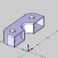
The Solid Shell function is used to remove one or more faces of a solidbody and recreate the solid with the specified wall thickness for theremaining surfaces.You can also shell the whole solid to create a closedhollow solid.
Navigation
To open Shell Solid:
- In the Modify group, of the Create 3D tab, click
 Shell.
The parameters display in theData Entry Manager.
The Data Entry Parameters
Geometry Selection
-
 Whole Solid- With this check box cleared, selection mode will be set to individualsurface faces only.
![]() Whole Solid - With this check boxselected, selection mode will be set to solid bodies only.
Whole Solid - With this check boxselected, selection mode will be set to solid bodies only.
Selected Geometry
|
|
|
| The list will display all entities currently selected for the function. | |
 (Delete All)
- removes all entities from the Selected Geometry list.
(Delete All)
- removes all entities from the Selected Geometry list.Direction
The direction parametersdetermine which way the shelled solid is created from the original solid.
-
 Inward - when this option is selected, theshell will be created by offsetting inward from the original geometry.
 -
 Outward - - when this option is selected,the shell will be created by offsetting outward from the originalgeometry.
Parameters
-
WallThickness - is the thickness for the resulting surfaces ofthe shelled model.
-
 Fillet Edges - creates fillets for all resultingshelled surface edges.This option uses the Wall Thickness parameterfor the fillet radius.
![]() Fillet Edges - doesnot create fillets.
Fillet Edges - doesnot create fillets.
Important: TheFillet Edges parameter is applied to outward shell creation, and is veryimportant for creating successful shelled surfaces.Turning this optionon or off can often resolve failed calculations.The Fillet Edges optionuses the Wall Thickness as the fillet radius so the dimensions of theoriginal solid must allow this radius to be applied.
- Show Preview / Hide Preview
Once geometry has been added to the SelectedGeometry list, selecting this toggle will enable, and disable the CADpreview, which displays the result that will be created when you clickOK.
- OK - finalizes the function.
- Cancel - exits the function.
Quick Steps - Shell Solid
-
Open the function and define all Data Entryparameters.
-
Click to select one or more faces of thesolid that you want to remove.
You can perform the function on one or more solids. -
Once geometry is added to the Selected Geometrylist, click Show Preview to see a preview of the result.
-
If needed, update the Data Entry parameters.
The changes update the CAD preview. -
Click OKto create the shell.
The feature is added to the CAD Tree. -
Repeat this process as needed for any othersolids, if you want to create another shell with different parameters.
-
Click Cancelto close the function.
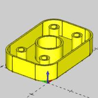
Example
A BobCAD file installed with the software can be opened to follow alongwith this example.
Part 1) Open the Example File
-
In the Quick Access Toolbar, click
 Open.
Open. -
Navigate to: C:\BobCAD-CAMData\BobCAD-CAM V**\Examples, and select ShellSolid Example.bbcd.
-
With ShellSolid Example.bbcd displaying in the FileName box, click Open.
Part 2) Open Shell Solid
To open Shell Solid:
- In the Modify group, of the Create 3D tab, clickShell.
The parameters display in theData Entry Manager.
Part 3) Create a Shelled Solid
For this example, we select the geometry first to create the CAD Previewbefore updating the Data Entry parameters.This allows us to visualizethe effect of each parameter and the result before actually creating it.
-
Click to select the top face of the partas seen in the image below.
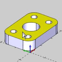
The selected face is added to the Selected Geometry list. -
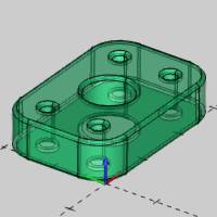
Click ShowPreview to create the CAD preview.
-
In the Data Entry Manager, under Direction,click Outward.
The Direction option determines to which side of the original surfacesthe Wall Thickness is applied.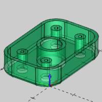
-
Double-click in the WallThickness box, to select all the text, and type 0.0625.
Press Tab or click anywherein the graphics area to update the CAD preview.
The Wall Thickness is applied to all surfaces and it also determinesthe radius value when using the Fillet option.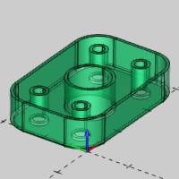
-
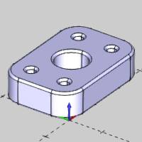
To shell the solid as shown in the CAD preview,click OK.
The Shell is created in the graphics area and a Shell feature is created inthe
  CADTree.
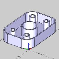
-
Click Cancelto close the Data Entry Manager.
Part 4) Modifying the Feature Using the CAD Tree
After using Shell Solid, a feature is created and added to the CAD Treeto allow for modification and more as explained in the CADTree.When you cancel the function, the CAD Tree Manager automaticallydisplays.Notice the Shell feature in the CAD Tree.
-
Click the Shellfeature in the CAD Tree and notice that the result highlightsin the Workspace.
-
Next to Shell,click
 to expand thefeature.
The Geometry item containsa right-click shortcut menu that can be used to modify the selectionand update the feature.For this example, we edit the feature to showhow to use Shell Whole Solid. -
Right-click Shell,and click Edit Parameters.
The Edit Parameters option opens the functionwith the geometry preselected for you to change only the parameters.Ifyou use the Edit option, the function is opened without the geometry preselected.
Part 5) Using Shell Whole Solid
You can also use the Shell Whole Solid option to create a hollow solidbody.When using this option, no faces are removed from the model.
-
In the Data Entry Manager, click WholeSolid.
In this scenario, changing to Shell Whole Solid clears the geometryselections, because we are changing the way that the Shell functionworks by changing the selection mode. -
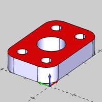
Click to select the flange in the graphicsarea.
Notice that you can now only select the entire solid, not separatefaces as earlier.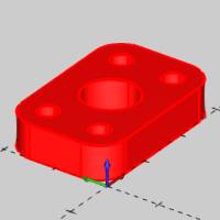
-
Press the ShowPreview button to create the CAD preview.
-
Click OKto shell the whole solid.
The Data Entry Manager is automatically closedwhen you click OK after editing.
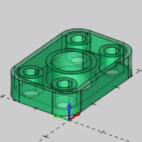
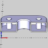
About the Shell Whole Solid Result
When using the Shell Whole Solid option, the result is not easy to visualizebecause you are creating a hollow solid.After using Solid Split on ourshelled solid, you can easily see the part is a hollow solid model.
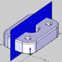
This concludes the example.