


 Advanced Holes
Introduction
This topic will explain the Advanced Holes function, will explain whereto find the function, and explain the options found in it.This topicwill also explain creation with quick steps and an example, and provide links to relatedtopics.
The Advanced Holes Function
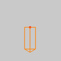
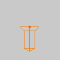
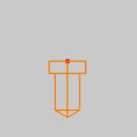
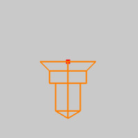
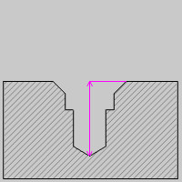
The Advanced Holes function is used to create a profile of the intended holes at chosen points, revolve their form, subtract them from a solid, and assign thread values as needed.In the images below you see the various hole forms that are possible to create with the Advanced Holes function.With each of the below forms, any could be assigned thread values in order to have them recognized as tapped holes by the Hole Recognition feature.
| Holes | Holes with Chamfer | Holes with Counterbore | Combination Holes |
|
|
|
|
Important: By default, Advanced Holes function is applied to all intersecting bodies in the file, unless they are hidden using the ![]() Blank function in the document toolbar, or the Selected Bodies option is used to specify the bodies to interact with.Without the Selected Bodies option, hiding a layer does not excludethe entities on that layer from being affected by the Advanced Holes.
Blank function in the document toolbar, or the Selected Bodies option is used to specify the bodies to interact with.Without the Selected Bodies option, hiding a layer does not excludethe entities on that layer from being affected by the Advanced Holes.
Navigation
To open the Advanced Holes function:
- In the Solid Boolean group, of the Create 3D tab, clickAdvanced Holes.
The parameters display in theData Entry Manager.
The Data Entry Parameters
 Sections
This section will allow you to use toggles to control what type of holes are being created.Any of these combinations can have thread added to them at the bottom of the dialog.
- Chamfer - With this toggle on, a chamfer is added to the hole.
- Counterbore - With this toggle on, a counterbore is added to the hole.
- Hole - This toggle is always on because we must have a hole.
Positions
This section will allow you to select the points that will dictate where the tops of the holes are located.These do not need to share the same height in Z, but all points picked at the same time will have the same hole type created for them.
Selected Geometry
|
|
|
| The list will display all entities currently selected for the function. | |
 (Delete All)
- removes all entities from the Selected Geometry list.
(Delete All)
- removes all entities from the Selected Geometry list.
Direction
By default the direction of the holes will be along the negative Z of the currently active UCS.This section will allow you to specify a direction of creation for the holes if it is needed.Select a point, snap point, line, edge, or surface to define the direction.
Selected Geometry
|
|
|
| This list box will show the entity currently selected for the function. | |
Chamfer
This section becomes available when the Chamfer toggle is selected in the Sections section at the top of the dialog.This section will allow you to specify the Included Angle of the chamfer along with, either the Top Diameter or Chamfer Depth.
Chamfer Type
-
 Top Diameter - will allow you to define the chamfer by using the top diameter and the included angle.
 -
 Chamfer Depth - will allow you to define the chamfer by using the chamfer depth and the included angle.
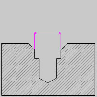
- Top Diameter - defines the uppermost diameter of the chamfer.
- Chamfer Depth - defines the distance between the top and bottom of the chamfer.
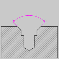
- Included Angle - defines the total angle between one wall of the chamfer and the opposite wall.
Counterbore
This section becomes available when the Counterbore toggle is selected in the Sections section at the top of the dialog.This section will allow you to specify the Diameter and Depth of the Counterbore.
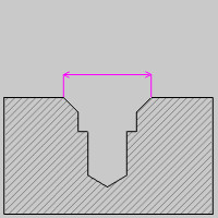
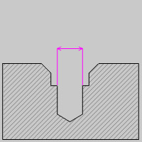
- Diameter - defines the total width of the counterbore.
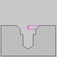
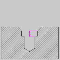
- Depth - defines the distance between the top and bottom of the counterbore.
Hole
This section will allow you to set the Diameter, Tip Angle, and the Total and Effective Depth of the hole.This section also allows you to specify a thread type if one is necessary.
- Diameter - defines the width of the hole.
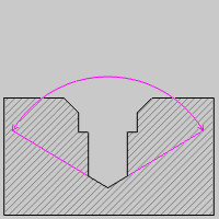
- Tip Angle - defines the angle of the intended drill tip.
- Effective Depth - defines the distance between the top of the hole and the beginning of the tip angle.
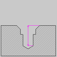
- Total Depth - defines the distance between the top of the hole and the bottom of the hole, including the tip angle.
Thread
![]() - With this check box cleared, no thread information will be attached to the created holes.
- With this check box cleared, no thread information will be attached to the created holes.![]() - With this check box selected, you will have access to the Thread Type and Size so that the proper thread information can be attached to the created holes, and recognized when using the Hole Recognition feature.
- With this check box selected, you will have access to the Thread Type and Size so that the proper thread information can be attached to the created holes, and recognized when using the Hole Recognition feature.
- Thread Type - lists the current Thread Type associated to the feature.The drop down list will allow you to select from the Thread Types currently in your Thread Library.
- Thread Size - lists the current Thread Size associated to the feature.The drop down list will allow you to select from the Thread Sizes currently in your Thread Library.
 Scope
Scope
-
All Bodies - With this option selected, all intersecting solid bodies not set to a
 Blank state will be affected by this feature. This includes bodies on layers set to a hidden state.
 -
Selected Bodies - With this option selected, only those intersecting solid bodies added to the selected geometry list below will be affected by this feature.
Selected Geometry
|
|
|
| This list box will show the entities currently selected for the function. | |
- OK - finalizes the function.
- Cancel - exits the function.
Quick Steps - Advanced Holes
- Open the function and choose the Sections to be included in the holes to be created first.
- Select the points you intend to make the first hole from.
The selection mask is automatically updated to select nothing but points, so you do not need to be cautious about selecting other entity types. - Once the points are added to the Selected Geometrylist, a preview is shown.If you need to change the direction the hole is being created in, click in the Selected Geometry list of the Direction section, and select geometry.The holes being created will align to the selected geometry.
- If needed, update the values in the Chamfer, Counterbore, and Hole sections.
The CAD preview updates automatically as changes are made. - Update the Scope section as needed to include/exclude the desired bodies.
- Click OKto create the holes.
The feature is added to the CAD Tree. - Repeat this process as needed for any otherholes.
- Click Cancelto close the function.
Example
If you are connected to the Internet, the part file for this example can be downloaded automatically by clicking the following link: Advanced Hole Example.bbcd
Once you download and saved the zip file, extract the files on your system in an easy place to remember.You can then open the file to use with this tutorial.All files for the tutorials in this help system available for download can be found by clicking on the following link: http://www.bobcad.com/helpfiles.
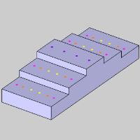
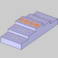
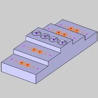
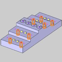
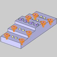
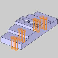
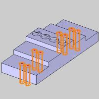
In the example file provided, a solid has been created with color coded points to dictate the location of the various holes we will be creating.
Part 1) Shallow Pockets
- In the Solid Boolean group, of the Create 3D tab, clickAdvanced Holes.
The Advanced Holes dialog opens in the Data Entry Manager.The focus is automatically on the Selected Geometry group, selection mode is active, and selection is filtered to allow the selection of points only. - In the Quick Selection group, of the Home tab, click
 Pick By Layer, and choose
  Pick By Color.
The Select Color dialog appears. - Select Purple, and click OK.
The points are added to the Selected Geometry list, and the Preview appears in the graphics area. - In the Hole section, update the Diameter to 0.875.
- Set the Tip Angle to 180.

- Update the Effective Depth to 0.125.
- Leave the Scope section set to All Bodies.
- Click OK.
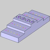
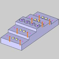
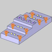
Part 2) Through Holes
- In the Quick Selection group, of the Home tab, click Pick By Layer, and choose Pick By Color.
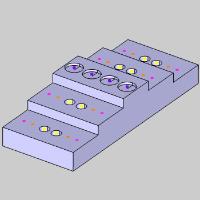
The Select Color dialog appears. - Select Yellow, and click OK.
The points are added to the Selected Geometry list, and the Preview appears in the graphics area. - In the Hole section, update the Diameter to 0.50.
- Update the Tip Angle to 118.
- Update the Effective Depth to 2.0.
- Click OK.
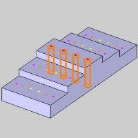
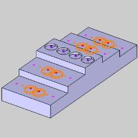
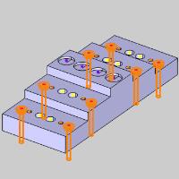
Part 3) Tapped Holes
- In the Quick Selection group, of the Home tab, click Pick By Layer, and choose Pick By Color.
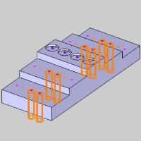
The Select Color dialog appears. - Select Orange, and click OK.
The points are added to the Selected Geometry list, and the Preview appears in the graphics area. - Update the Effective Depth to 0.75.
- Select the check box for Thread.
The Preview updates to show the default thread size. - Set the Thread Size to UNC 1/4 - 20.
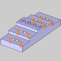
- Click OK.

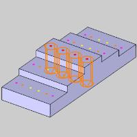
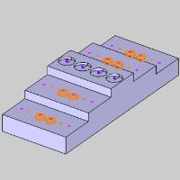
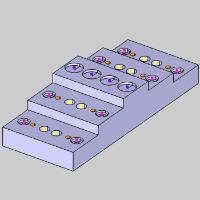
Part 4) Counterbore Holes
- In the Quick Selection group, of the Home tab, click Pick By Layer, and choose Pick By Color.
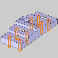
The Select Color dialog appears. - Select Pink, and click OK.
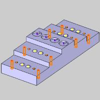
The points are added to the Selected Geometry list, and the Preview appears in the graphics area. - At the top of the dialog, select the Chamfer, and Counterbore buttons.

The Preview updates. - In the Chamfer section, select Chamfer Depth for the Chamfer Type.
- Set the Chamfer Depth to 0.05.
- In the Counterbore section, set the Diameter to 0.375.
- In the same section, set the Depth to 0.125.

- In the Hole section, set the Effective Depth to 2.0, and clear the Thread check box.
- Click OK, and then Cancel.
Part 4) Update the Through Holes
- Since we are finished creating holes, we no longer need the points.
In the Layers Manager, hide the Points layer.
- In the CAD Tree Manager, right-click the second Advanced Holes feature and select Edit.
The Advanced Holes dialog opens in the Data Entry Manager with the points in the Selected Geometry list.
The Preview is also shown, and any Advanced Holes features completed after this feature are hidden.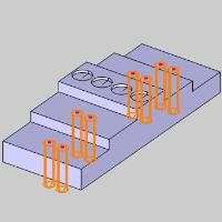
- Select the Chamfer button at the top of the dialog.
The Preview updates to show the default Chamfer size. - In the Chamfer section, select Chamfer Depth for the Chamfer Type.
- Set the Chamfer Depth to 0.05.
- Click OK, and then Cancel.
The model does not show the updates. - In the CAD Tree Manager, right-click the top item and select Rebuild.
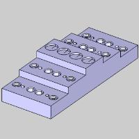
The model updates to reflect the chamfers.
This concludes the example.