


 Edit Property
Introduction
This topic will explain the Edit Property function, and the optionsfound in it.This topic will also describe where to find the function,provide quick steps on how to use it, and provide links to related topics.
The Edit Property Function
The Edit Property function is used to adjust the assigned thread values of particular geometry which BobCAD-CAM can later read when the geometry is chosen for features.
Navigation
To open the Edit Property dialog:
- In theEdit Property.
The parameters display in theData Entry Manager.
The Data Entry Parameters
Type
-
 Thread - by default the thread type is selected to be assigned to the selected geometry.
Filter
- Thread Size - lists all of the current Thread Sizes found in the file.The drop down list will allow you to limit the geometry listed to only that of the particular thread size.
- The geometry list will show all geometry associated to the thread size selected for the filter.Unless all geometry in the list is to be updated, use Ctrl and/or Shift to select all of the geometry to be updated with new thread information.
-
 (Delete) - removesthe highlighted item from the list.
 -
 (Delete All) - removes all entities from the list.ist.
 Update
Thread Information
- Thread Type - lists the current Thread Type associated to the feature.The drop down list will allow you to select from the Thread Types currently in your Thread Library.
- Thread Size - lists the current Thread Size associated to the feature.The drop down list will allow you to select from the Thread Sizes currently in your Thread Library.
- Update All - updates each geometry item in the list with the currently selected Thread Type and Size.
- Update Selected - updates only the highlighted geometry items in the list with the currently selected Thread Type and Size.
- Cancel - exits the function.
Quick Steps - Add Property
- Open the function.
- In the Filter group, select the thread size to be found in the file.
The geometry list is updated to include only the entities which have that particular thread size assigned. - Select the geometry which is to have updated thread information assigned.
If all geometry in the list is to be updated with the same thread information, selecting all items in the list is not necessary. - Update the thread information to what thread type and size should be updated for the selected geometry.
- With the correct geometry selected, and the proper thread information ready to be updated click Update Selected.
If all geometry in the list was to updated with the same thread information, you would click Update All. - Repeat as necessary for any other thread sizes which need to be edited.
- Click Cancel to close the function.
Example
Example File
The part file for this example is the result of the example used in the Property Add topic.If you have not yet completed that example, take a moment to do so.Once completed, leave the part open in its final state, then return to complete this example.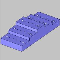
Part 1) Open the Edit Property function
- In the Edit Property.
The function opens in the Data Entry Manager.
By default the focus is on the Selected Geometry list and Selection Mode is active to allow you to add geometry to the list.
Part 2) Edit Properties for a UNC 3/8 - 16 Thread
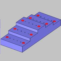
- With UNC 3/8 - 16 selected for the Thread Size in the Filter group, all of the large holes are highlighted.
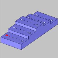
In the geometry list, select Face 48-23
The bottom left hole highlights.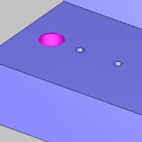
- In the Thread Information group of the Add Property dialog:
- Leave the Thread Type defaulted to UNC.
- Set the Thread Size to UNC 1/4 - 20.
- Leave the Thread Type defaulted to UNC.
- Click Update Selected.
The Properties are updated, and the hole is no longer selected.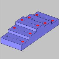
This is because we have created a new Thread Size but are still filtering editable thread sizes by UNC 3/8 - 16.
Part 3) Edit Properties for a UNC 5-40 Thread
- In the Filter group, select UNC 5-40 for the Thread Size.
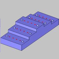
All of the small holes are highlighted. - In the geometry list, select Face 48-43
The small hole on the bottom left highlights.
- In the Thread Information group of the Add Property dialog:
- Leave the Thread Type defaulted to UNC.
- Set the Thread Size to UNC 1/4 - 20.
- Leave the Thread Type defaulted to UNC.
- Click Update Selected.
The Properties are updated, and the hole is no longer shown in our Thread Size Filter.
- In the Filter group, select UNC 1/4 - 20 for the Thread Size.
We can see only the geometry we edited properties before are shown using this filter.
This concludes the example.