


Entity Modification
Introduction
This topic will explain Entity Modification, provide quick steps on how to use it, and provide links to related topics.
Entity Modification
There are numerous ways to modify geometry in the graphics area. This help topic explains the functions used for changing the attributes and parameters of entities besides those like Translate, Rotate, Mirror, and the like, found in the Utilities Ribbon. Most of these functions are not available until an entity is selected in the graphics area.
Navigation
To access the Entity Modification functions do one of the following:
-
Select the desired entity or entities, and right-click in the graphics area. Then click Modify To Current, Modify Entities, or *Entity Modify.
-
*Entity Modify can be utilized without the need to select the entity first using a double-click short-cut. In Selection Mode, double-click the desired entity and the appropriate Modify dialog is opened automatically.
-
-
In the Modify group, of the Home ribbon, click the icon of the desired function.
The Entity Modify Functions
Modify Entity Attributes
For the following functions, you must first select an entity, and then select one of the following.
- Color - opens the Modify Color dialog box. Click the new color, and the selected entity is updated.
- Layer - opens the Select Layer dialog box. Click the layer to which the selected entity is moved, and click OK.
- Line Style - opens the Line Style dialog box. Click the new line style to apply to the selected entity, and click OK.
- Point Style - opens the Point Style dialog box. Click the new point style to apply to the selected entity, and click OK.
Modify Entity To Current
The following functions are used with the current software settings, such as the current color and line style that are displayed (and can be changed) in the Status Bar at the bottom-right side of the user interface. The current settings must be different than that of the selected entity to use these functions.
-
 Modify to CurrentColor
- changes the selected entities to the active color.
Modify to CurrentColor
- changes the selected entities to the active color. -
 Modify to Current Line Style - changes the selected
entities to the active line style.
Modify to Current Line Style - changes the selected
entities to the active line style. -
 Modify to CurrentLayer
- places the currently selected entities on the active layer.
Modify to CurrentLayer
- places the currently selected entities on the active layer. -
 Modify
to Current Point Style - changes the selected points to the
current point style.
Modify
to Current Point Style - changes the selected points to the
current point style.
Change Line Style
-
 Change Style to Solid - converts selected entities
to a solid line style.
Change Style to Solid - converts selected entities
to a solid line style. -
 Change Style to Dashed - converts selected entities
to a dashed line style.
Change Style to Dashed - converts selected entities
to a dashed line style.
Entity Modify
-
 Entity Modify - opens the
Data Entry Manager so you can modify the parameters of the selected
entity. You must select a single entity (whether or not it is a part
of a contiguous entity chain), such as one line or one arc, or this
function is unavailable. This option is used for wireframe entities,
including text. To learn more, view How
to Modify Wireframe Entities.
Entity Modify - opens the
Data Entry Manager so you can modify the parameters of the selected
entity. You must select a single entity (whether or not it is a part
of a contiguous entity chain), such as one line or one arc, or this
function is unavailable. This option is used for wireframe entities,
including text. To learn more, view How
to Modify Wireframe Entities.
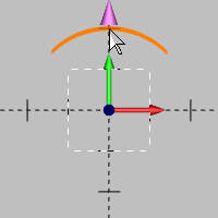
Quick Edit
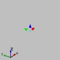
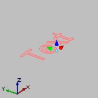
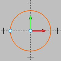
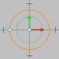
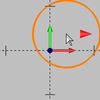
When modifying points, lines, arcs, and text, the Quick Edit becomes available allowing you to use the mouse to update various entity definition values based on entity type. When first modifying the entity only the available origin spheres will be visible. Hovering over one of the available origin spheres will display the Quick Edit allowing you to modify the specific value of the entity. The images below show each entity type with all of their Quick Edits visible for clarification.
| Point | Line | Arc (Full) | Arc (Partial) | Text |
|
|
|
|
|
-
 Origin Sphere - Hover over the control to view the available controls, or:
-
Point - Moves point with full range of freedom.
-
Line :
-
Start Point - Moves the start point with full range of freedom while keeping the end point fixed.
-
End Point - Moves the end point with full range of freedom while keeping the start point fixed.
-
Mid-Point - Moves entire line with full range of freedom.
-
-
Arcs :
-
Full Circle :
-
Arc Center - Moves entire arc with full range of freedom.
-
Mid-Point - Gives you access to the size control which modifies the diameter/radius of the arc while keeping the arc center fixed.
-
-
Partial Arc :
-
Arc Center - Moves entire arc with full range of freedom.
-
Start Point - Moves entire arc with full range of freedom.
-
End Point - Moves entire arc with full range of freedom.
-
Mid-Point - Gives you access to the size control which modifies the diameter/radius of the arc while keeping the arc center fixed.
-
-
-
Text - Moves the text with full range of freedom.
-
-
The Cones :
-
 X - Moves the entity along the X axis of the active UCS.
 -
 Y - Moves the entity along the Y axis of the active UCS.
 -
 Z - Moves the entity along the Z axis of the active UCS.
 -
 Size - Varies based on entity type and location on the entity:
 -
Point - Not applicable.
-
Line :
-
Start Point - This control modifies the length of the entity while keeping the end point fixed.
-
End Point - This control modifies the length of the entity while keeping the start point fixed.
-
Mid-Point - Not applicable.
-
-
Arcs :
-
Full Circle :
-
Arc Center - Not applicable.
-
Mid-Point - This control modifies the diameter/radius of the arc while keeping the arc center fixed.
-
-
Partial Arc :
-
Arc Center - This control modifies the diameter/radius of the arc while keeping the endpoints fixed.
-
Start Point - This control modifies the start angle of the arc.
-
End Point - This control modifies the end angle of the arc.
-
Mid-Point - This control modifies the diameter/radius of the arc while keeping the arc center fixed.
-
-
-
Text - Not applicable.
-
-
Other Modification Tools
To learn how to rotate, trim geometry, move in other ways, and alter geometry in many other ways, view the Utility Functions. Dynamic changes can be made with the utilization of The CAD Tree.
Examples
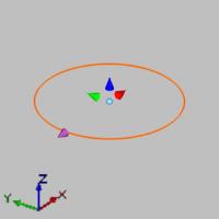
Example 1) Modify a Full Arc
For this example, we will use manual data entry, and Quick Edit.
Part 1) Using Manual Data Entry
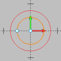
The following image shows an arc with a 0.750 inch radius that we want to change to a 0.500 inch radius. If you are already familiar with entity modification with manual data entry in the dialogs, skip to Part 2.
To modify this entity by entering new values, we use the following steps.
-
In the document toolbar, click
 Select Mode.
 -
Point to the arc in the graphics area, so that it displays in the system highlight color, and double-click to open the Modify Arc dialog in the Data Entry Manager.
The Modify Arc dialog opens, and the preview and Quick Edit appears.
Note: You can also click once to select the entity, then right-click anywhere in the graphics area, and select Entity Modify. However the dialog is opened, any of the available parameter values can now be updated as needed. These values can be updated manually in the dialog, or in the graphics area using the Quick Edit. For this part of the example, we only change the radius using manual data input.
-
In the Modify Arc dialog, change the Radius value to 0.500, and press Tab to update the CAD preview.
-
To finish modifying the entity, click OK.
The Modify Arc dialog is closed and Selection Mode remains active.
Note: Manual data entry can be used to change any of the arcs parameters in the Data Entry Manager.
Part 2) Using Quick Edits
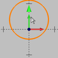
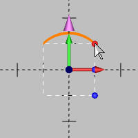
Adjusting the Radius
-
Double-click the arc.
The Modify Arc dialog opens in the Data Entry Manager, and the preview and Quick Edit appears. -
Hover over the modification sphere attached to the radius.
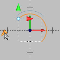
The Size arrow becomes available. -
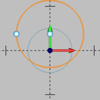
Hover over the arrow to highlight it.
-
Click the arrow.
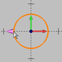
The preview snaps to the pointer allowing you to adjust the radius freehand, or by utilizing the snap points of another entity. -
Move your mouse a little to adjust the radius, and click to place.
The Modification Spheres become available again.
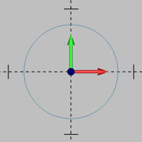
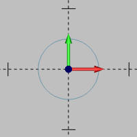
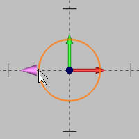
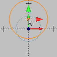
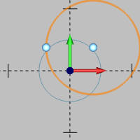
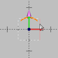
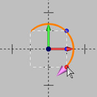
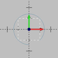
Adjusting the location: Y Axis cone
-
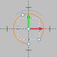
Highlight the center origin sphere this time.
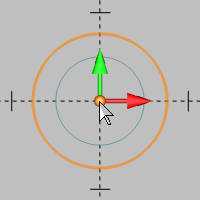
Notice X Axis and Y Axis cones are shown.
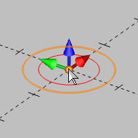
Shifting to an isometric view would reveal the Z Axis cone as well. -
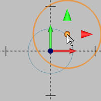
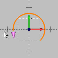
Hover over the Y Axis cone and click it.
The preview center snaps to the pointer allowing you to adjust the Y Axis location of the arc center freehand, or by utilizing the snap points of another entity.
Notice the arc center is locked in the X Axis but can be moved freely along the Y axis. -
Click to set the location in the Y Axis.
The Modification Spheres become available again.
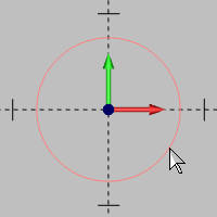
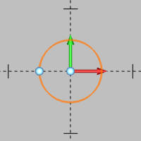
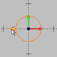
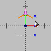
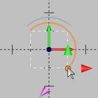
Adjusting the location: X Axis Cone
-
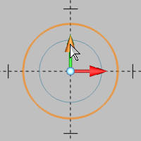
Hover over the center origin sphere to show the X Axis cone, then highlight and click it.
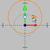
Notice the arc center is now locked in the Y Axis but can be moved freely along the X axis. -
Click to set the location in the X Axis.
The Modification Spheres become available again.
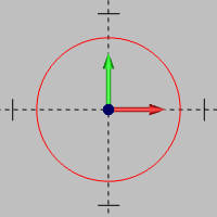
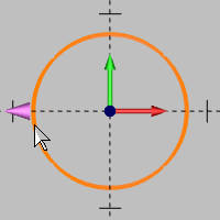
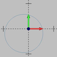
Adjusting the location: Center Origin Sphere
-
This time, we move the arc freely along the X and Y by highlighting, and clicking, the center sphere.
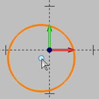
Once moved, click again to place the arc.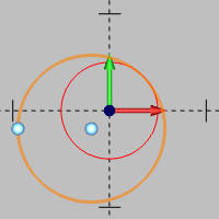
-
Click OK to finalize the modification and close the dialog.
The dialog closes and Selection Mode is left active for any other modifications which may be needed.
This same process can be applied to modify point, line, or text entities.
Note: If you have created text with the Vectorize option turned off, you can modify the parameters for that text entity, including the letters. If the vectorize option was turned on when creating the text, then only the individual line and arc entities of the text can be modified.
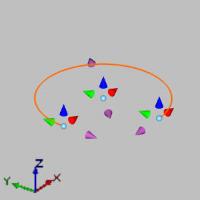
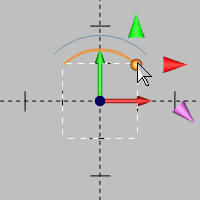
Example 2) Modify a Partial Arc
In this example, we modify a partial arc, and utilize the snap points of a previously created square.
Adjusting the Radius
-
Enter into Selection Mode.
-
Double-click the arc.
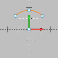
The Modify Arc dialog opens in the Data Entry Manager, and the preview and Quick Edit appears. -
Hover over the middle modification sphere attached to the radius to access the size arrow and adjust the radius value.
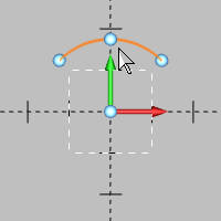
The Size arrow becomes available. -
Hover over the arrow to highlight it.
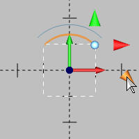
-
Click the arrow.
The preview snaps to the pointer allowing you to adjust the radius freehand, or by utilizing the snap points of another entity. -
Move your mouse to the entity whose snap points you wish to utilize.
-
Highlight the proper snap point and click to set the radius.
Since our mouse is still hovering about the modification sphere, the available arrows are shown.
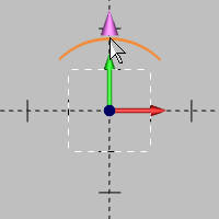
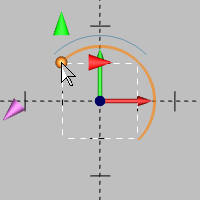
Adjusting the Start Angle
-
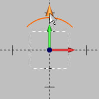
Hover over the Size arrow to highlight it, and then click it.
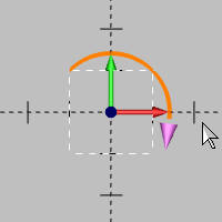
The preview snaps to the pointer allowing you to adjust the start angle freehand, or by utilizing the snap points of another entity. -
Move your mouse to the entity whose snap points you wish to utilize.
-
Highlight the proper snap point and click to set the Start Angle.
Since our mouse is still hovering about the modification sphere, the available arrows are shown. Moving your mouse away hides the arrows and shows possible modification spheres once more.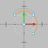
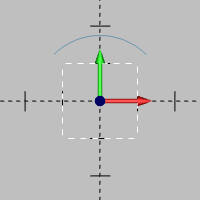
Adjusting the End Angle
-
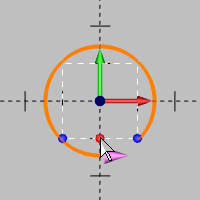
Next, we adjust the End Angle, so highlight the modification sphere on the left of the radius.
The arrows become available. -
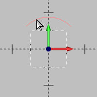
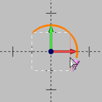
Hover over the Size arrow to highlight it, and then click it.
The preview snaps to the pointer allowing you to adjust the start angle freehand, or by utilizing the snap points of another entity. -
Move your mouse to the entity whose snap points you wish to utilize, in this case, the middle snap point of the bottom horizontal line.
-
Click to set the End Angle.
The Modification Spheres become available again.
-
Click OK to confirm the changes.
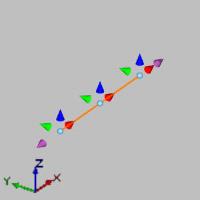
Example 3) Modify a Spline
When you modify a spline, the process is slightly different than other entity types. Modifying a spline allows you to change the spline control points.
The following image show a surface that was extruded from a spline curve.
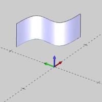
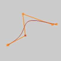
To modify the spline that created the surface, we use the following steps.
-
In the CAD Tree, we right-click our Extrude Curve feature, and click Suppress/Unsupress.
This suppresses the extrude curve feature so that only the wireframe displays. Note that this step isn't necessarily required. If the spline is created on one CAD layer and the surface is on another CAD layer, we can just hide the surface layer. Also, the blank function can be used to hide the surface temporarily. Either way, we just need to make the spline visible so we can select it.
-
On the document toolbar, click the
 Select Mode icon.
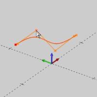
Click to select the spline in the graphics area.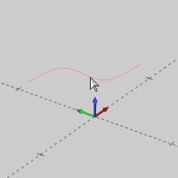
Notice again, that the entire spline highlights when we point to it. This is how we know it is a single entity, and thus can be modified. -
In the Modify group, of the Home ribbon, click
Entity Modify.
The Modify Curve dialog displays in the Data Entry Manager, and the CAD preview displays in the graphics area.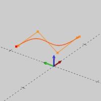
Notice the control points that display. You click these points to enable modification and then click to place them, or change their values in the Coordinate group of the Data Entry Manager. -
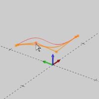
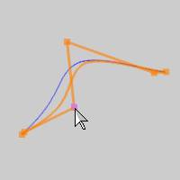
Next, click to select one of the control points so you can modify it.
-
Click anywhere to place the control point.
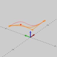
Note that you can also select a point or the snap point of another wireframe entity when modifying a spline control point.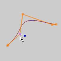
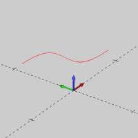
-
In the Data Entry Manager, click OK to finish modifying the spline.
-
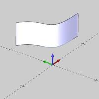
Now because we modified a wireframe entity that is the input to a surface feature (extrude curve), we need to update the Extrude Curve Feature.
Right-click the Extrude Curve feature in the CAD Tree, and select Suppress/Unsppress.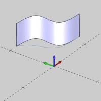
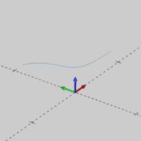
The surface reappears. - Right-click the Extrude Curve feature in the CAD Tree, and select Rebuild.
The surface is automatically rebuilt using the modified spline geometry.
Note: As long as we are changing the geometry that is already associated with a feature in the CAD Tree, we can simply rebuild. If we created new geometry, or needed to assign different geometry to it, we would need to right-click the geometry of the feature in the CAD Tree, choose Re/Select, then associate the new geometry before rebuilding.
This concludes the examples.