


 Rotate
Introduction
This topic will explain the Rotate function, and the optionsfound in it.This topic will also give brief description of Dynamic Drawing, the SnapIncrement function, will describe where to find the function,provide quick steps on how to use it, and provide links to related topics.
The Rotate Function
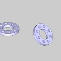
The Rotate function rotates geometry around a defined axis, with optionalcopying and/or scaling, using Dynamic Drawing.Dynamic Drawing allowsyou to use data entry or sketch handles to define the rotation anglesand rotation origin.The benefit of Dynamic Drawing is that both methodscan be utilized at any time during creation.You can use the sketch handlesto get close to the desired result and then update the Data Entry parametersto get the exact value.
Dynamic Drawing
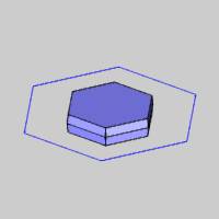
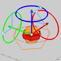
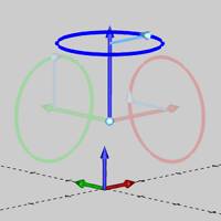
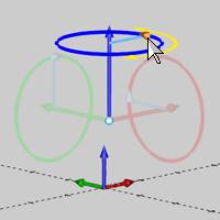
This function supports Dynamic Drawing which allows you to use a combination of sketching and data entry to create the entities. Prior to confirming the desired result in the function, an adjustable preview is visible. These previews can be modified using the sketch handles, data entry, or a combination of both. The benefit of Dynamic Drawing is that you can quickly utilized the sketch handles to adjust the size, placement, and, or, orientation to get the approximate result, and then use data entry to update to the exact values as needed.
|
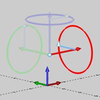
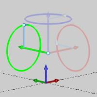
Preview with Sketch Handles |
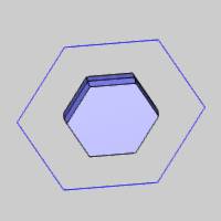
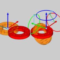
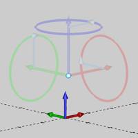
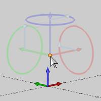
Final Entities |
|
|
In the images above, we see the preview of the altered position / orientation of the entities which can be adjust with sketch handles, followed by those same entities after their positions / orientations are finalized.
Snap Increment
This function support the use of the snap increment when selecting the location of the entities. The snap increment allows you to get precise results when using mouse selection and helps to reduce data entry modifications.
To learn more, view Snap Increment.
Navigation
To open Rotate:
- In the Move group of the Utilities ribbon,click
 Rotate.
The parameters display in theData Entry Manager.
The Data Entry Parameters
 Type
Type
-
 Rotate
-
 Rotate 3D
Selected Geometry
|
|
|
| The list will display all entities currently selected for the function. | |
 (Delete All)
- removes all entities from the Selected Geometry list.
(Delete All)
- removes all entities from the Selected Geometry list.Angle Around Axis
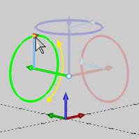
The Angle Around Axis parameters allow you to define the amount of rotationaround each of the three coordinate axes: X, Y, and Z. Dynamic Drawingallows you to modify these parameters using data entry, sketch handles,or a combination of both.When using sketch handles, the snapincrement applies.
Tip: The RotationAngle sketch handles points in the positive direction of rotation basedon the right-hand rule.
- X - determines the amountof rotation around the X-axis of the Active UCS.You can use the sketchhandle or type the value to define the amount of X-axis rotation.

- Y - determines the amountof rotation around the Y-axis of the Active UCS.You can use the sketchhandle or type the value to define the amount of Y-axis rotation.
- Z - determines the amountof rotation around the Z-axis of the Active UCS.You can use the sketchhandle or type the value to define the amount of Z-axis rotation.
Rotation Center
The origin parameters define the center of rotation for the selectedgeometry.You can use the origin handle to set the origin by selectingthe snap point of another entity or any arbitrary location in the workspace,or you can type values in the Data Entry Manager to define the originlocation.Dynamic Drawing provides the ability to do both.When usingthe origin handle, the snap incrementapplies.
-
X - determines the X-axislocation of the rotation origin in reference to the active UCS.
-
Y - determines the Y-axislocation of the rotation origin in reference to the active UCS.
-
Z - determines the Z-axislocation of the rotation origin in reference to the active UCS.
Options
- Copies - adds the specifiedamount of copies consecutively to the rotated geometry instead ofonly rotating the original geometry.When using copy, the originalgeometry is not rotated.
- Scale - scales therotated geometry by the amount typed in the Scale box.A value ofone equals no scaling and a value of 0.5 means fifty percent of theoriginal size.
- OK - finalizes the function.
- Cancel - exits the function.
Quick Steps - Rotate
- Open the function.
The Selected Geometry list automatically has focus. - Select the geometry to be rotated.
The geometry is added to the Selected Geometry list, and the sketch handles appear. - Define the Rotation Angle, and the Rotation Axis.
The preview updates. - With the preview showing the desired result, click OK.
Note: When this feature is applied to solids, or surfaces, a CAD feature is added to the CAD Tree.
- Repeat as necessary.
Tip: Instead of applying features to solids and surfaces more than once, go to the CAD Tree to edit the existing feature. Since all solid and surface moves, and modifications are stored in the CAD Tree, editing a feature is preferable to adding many more to achieve the desired result. This will keep file size down and help ensure files don't become slow to respond.
-
Click Cancel to close the function.