


 Scale
Scale
Introduction
This topic will explain the Scale function, and the optionsfound in it.This topic will also give brief description of Dynamic Drawing, the SnapIncrement function, will describe where to find the function,provide quick steps on how to use it, and provide links to related topics.
The Scale Function
The Scale function is used to scale (resize) wireframe or solid entitieswith separate scaling factors for each of the three coordinate axes.
Note: Touse Scale on text entities, you must either create them using the Vectorizeoption, or you can use the Explode utility after creating non-vectorizedtext.Either method converts the text entities to lines and arcs so theycan be used with Scale.
Dynamic Drawing
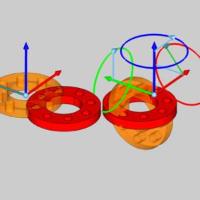
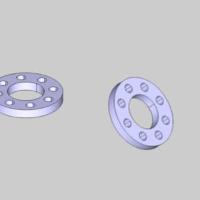
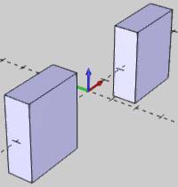
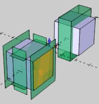
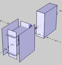
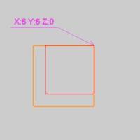
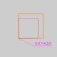
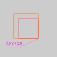
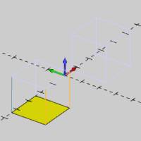
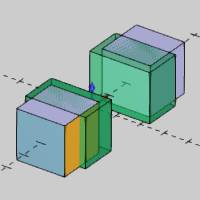
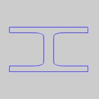
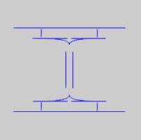
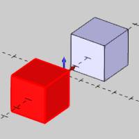
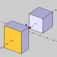
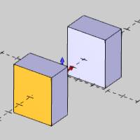
This function supports Dynamic Drawing which allows you to use a combination of sketching and data entry to create the entities. Prior to confirming the desired result in the function, an adjustable preview is visible. These previews can be modified using the sketch handles, data entry, or a combination of both. The benefit of Dynamic Drawing is that you can quickly utilized the sketch handles to adjust the size, placement, and, or, orientation to get the approximate result, and then use data entry to update to the exact values as needed.
|
Preview with Sketch Handles |
Final Entities |
|
|
In the images above, we see the preview of the altered position / orientation of the entities which can be adjust with sketch handles, followed by those same entities after their positions / orientations are finalized.
Navigation
To open Scale, do one of the following:
-
In the Move group, of the Utilities ribbon,click
 Scale.
The parameters display in the Data Entry Manager.
The Data Entry Parameters
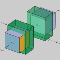
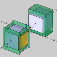
- Hide Selected Geometry
 - With this check box cleared, the selected geometry will remain visible in the graphics area while utilizing the feature.
 - With this check box selected, the selected geometry will not be visible in the graphics area while utilize the feature.
| Example Geometry | |

|
|
|
|
|
|
|
Scale Factors
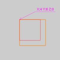
The scale factor determines the ratio of scaling applied to the geometry.A value of 1.00 is equal to no scaling,0.50 is equal to one half of the original size, and 2.00 is equal to twicethe original size.
-
 Uniform Scale - applies the scale factor to all axes equally.
|
Scale Factor - sets the scale to use on the selected geometry. |
-
 Non-Uniform Scale - allows for scaling factor to be applied to axes individually.
|
X - sets the scale in the X axis to use on the selected geometry. Y - sets the scale in the Y axis to use on the selected geometry. Z - sets the scale in the Z axis to use on the selected geometry. |
Scale Origin
-
Geometry Center - applies the scale factor origin to the center of the selected geometry.
Location Control
When the Scale Origin is set to Geometry Center, the Location Control group becomes available:
-
Scale All Entities Together - keeps all selected geometry in their relative positions to each other.
-
Scale Each Entity Individually - scales all geometry individually, regardless of their positional relationship to each other.
-
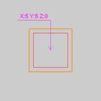
Enter - allows each axis of the scale factor origin to be controlled individually.
|
X - defines the X axis of the Scale Origin. Y - defines the Y axis of the Scale Origin. Z - defines the Z axis of the Scale Origin. |
- OK - finalizes the function.
- Cancel - exits the function.
Quick Steps - Scale
- Open the function.
The Selected Geometry list automatically has focus. - Select the geometry to be scaled.
The geometry is added to the Selected Geometry list, and the preview automatically displays. - Define all the parameters.
Note: To useScale on text entities, you must either create them using the Vectorizeoption, or you can use the Explode utility after creating non-vectorizedtext.
-
To finalize the scale, click OK.
If you want to scale more entities, update the Data Entry parametersand repeat this process as needed. -
To close the function, click Cancel.
If you selected solid or surface geometryto scale, a feature is added to the CAD Tree.
Example
A BobCAD file installed with the software can be opened to follow alongwith this example.
Part 1) Open the Example File
-
In the Quick Access Toolbar, click
 Open.
Open. -
Navigate to: C:\BobCAD-CAMData\BobCAD-CAM V**\Examples, and select NonuniformScale Example.bbcd.
-
With NonuniformScale Example.bbcd displaying in the FileName box, click Open.
About the Example Geometry
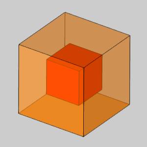
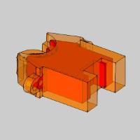
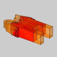
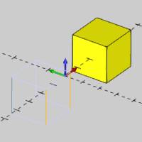
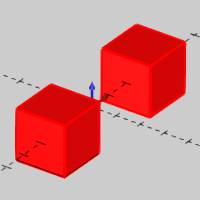
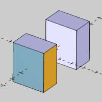
The example file contains two cubes, one of which is a single solidbody, and the other is unstitched meaning it is six separate surfaces(solid bodies).This is done to help illustrate the scaling options forthe function.
Before opening the function, we use the CAD Tree to visualize the solidbodies in the graphics area.
-
In the Data-CAMTree Manager, click the
 CAD Tree Manager tab.
 -
Next to
 Solids,click
  to expand thefolder.
 -
Click anywhere in the graphics area, to giveit key focus, and press Sto turn off the Shaded view.
-
Click Solid1 in the CAD Tree and notice the cube highlights in the graphicsarea.
-
Click each Solid itemin the CAD Tree to highlight the separate surface bodies in the graphicsarea.
You can see that one cube is a single entity,and the other cube is six separate entities.
Part 2) Open Scale
To open Scale:
-
In the Move group, of the Utilities ribbon,click
Scale.
The parameters display in theData Entry Manager.
Part 3) Using Scale
For this example, we select the geometry first to create the CAD preview.This allows us to view the result of the function before it is created.
-
Press Sto turn on the Shaded view.
-
Press Ctrl+Ato select all geometry in the graphics area.
Click OKto create the CAD preview.
It appears as if there is no CAD preview,because we have not yet defined a Scaling Factor (they are set to 1.00which means no scaling).
-
In the Data Entry Manager under ScaleFactor, double-click in the Xbox to select all the text, and type 0.750.
Press Tabto move to the Y box and update the CAD preview.
This setting scales the geometry to 75 percentof the original size in the X-axis only.
-
In the Y box, type 1.250 and press Tab.
This setting scales the geometry to 125 percentof the original size in the Y-axis only.
-
In the Z box, type 1.500 and press Tab.
Note: When scaling2D wireframe entities, only two of the Scale Factors can be used, basedon the drawing plane.For example, changing the Z-axis scale factor hasno effect on wireframe drawn in the XY plane.
Part 4) Using the Location Control Options
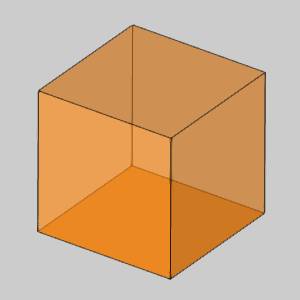
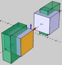
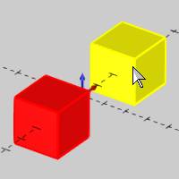
We have been using the default Location Control option, Scale All EntitiesTogether.This treats all selected geometry as a single unit to whichthe scaling is applied.You may notice that the CAD preview shows thecubes are moving away from their original location as a result of thecurrent Location Control option.Next we explore the Scale Each EntityIndividually option.
-
Under LocationControl, click Scale EachEntity Individually.
Notice the change in the CAD preview.Youcan see that the scaling is no longer moving the cubes away from theiroriginal location, because they are now being scaled as individual entities.You can also see that each surface of the unstitched cube is now alsobeing scaled individually.
![]() Tip:
Tip:
Usingthe Scale All Entities Together option maintains the relationship betweenmultiple entities when using scaling.This may be helpful whenscaling wireframe shapes, or as in this example, a cube made of separatesurfaces.
|
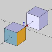
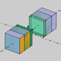
OriginalShape |
Scale AllEntities Together |
Scale EntitiesIndividually |
|
|
|
|
Note that both Location Control options providethe same result when scaling a single entity.
-
Change the Location Controlback to Scale All Entities Together.
-
To scale the entities as shown in the CAD preview, click OK.
-
Click Cancel to closethe Data Entry Manager.
Part 5) Modifying the Feature Using the CAD Tree
When you use Nonuniform Scale with solids, a feature is created andstored in the CAD Tree to allow for modification and more as explainedin the CADTree.When you cancel the function, the CAD Tree Manager automaticallydisplays.Notice the Nonuniform Scale feature in the CAD Tree.
For this part of the example, we decide that we want to scale each ofthe cubes individually.Next we use the CAD feature to change the geometryselection.
-
In the CAD Tree next to NonuniformScale, click
to expand the feature. -
Right-click
 Geometry,and click Re/Select.
 -
Click the single-entity cube to remove itfrom the selection.
-
Press the Spacebar toconfirm the selection.
Notice that the feature automatically rebuildswhen confirming the selection.
Now that we are scaling each cube separately,they retain their original location (the center of the cube doesn't change).
-
You can now create another Scale feature to scalethe other cube.
This concludes the example.