


The Document Toolbar
Introduction
This topic will describe the document toolbar, and explain the options found in it.
Document Toolbar
The Document Toolbar allows you to have the view options for the graphics area available to you no matter what ribbon is currently in use.
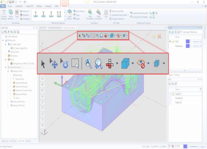
The Document Toolbar options
-
 Select
Mode - enables selection mode.
Select
Mode - enables selection mode. -
 Pan
- The Pan function is used to pan or move the current viewing position
in the graphics area. To perform the function, click Pan (the mouse
pointer changes to the pan icon), then click and drag the view to
the desired position, and then release the mouse button. To end the
function, click
Pan
- The Pan function is used to pan or move the current viewing position
in the graphics area. To perform the function, click Pan (the mouse
pointer changes to the pan icon), then click and drag the view to
the desired position, and then release the mouse button. To end the
function, click  Cancel (or press Esc).
 -
 Rotate -
The Rotate function is used to rotate or change the viewing
angle (around the center of the current viewing position) in the graphics
area. To perform the function, click Rotate, and then click and drag
the mouse to change the view. To cancel the function, click Cancel.
Rotate -
The Rotate function is used to rotate or change the viewing
angle (around the center of the current viewing position) in the graphics
area. To perform the function, click Rotate, and then click and drag
the mouse to change the view. To cancel the function, click Cancel. -
 Zoom
Window - The Zoom Window command is used to drag
a window in the graphics area and have the selected area expanded
to the full window size. To perform the command, click Zoom Window,
drag a window in the graphics area, and then release the mouse to
zoom in on the selected area.
Zoom
Window - The Zoom Window command is used to drag
a window in the graphics area and have the selected area expanded
to the full window size. To perform the command, click Zoom Window,
drag a window in the graphics area, and then release the mouse to
zoom in on the selected area. -
 Fit
All - The Fit All function is used to change the view of the
graphics area so that all geometry can be seen. When you click Fit All, the function is performed.
Fit
All - The Fit All function is used to change the view of the
graphics area so that all geometry can be seen. When you click Fit All, the function is performed. -
 Zoom
Previous - The Zoom Previous command returns
to the last view perspective used.
Zoom
Previous - The Zoom Previous command returns
to the last view perspective used. -

|

|
|
|

|
|
|

|
|
|

|
|
|

|
|
|

|
|
|
||
|

|
|
|

|
|
|

|
|
|

|
|
|

|
|
|

|
|
|

|
|
|

|
|
-

-
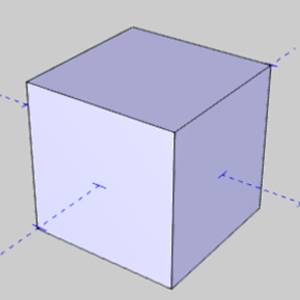
Shaded
- The Shaded function is used to toggle the view of solids/surfaces,
in the graphics area, between a surface view or wireframe view.
To perform the function, click Shaded. To return, click Shaded
a second time.
 View
an example
View
an example
-
 Transparent
- The Transparent function is used to make solids/surfaces in
the graphics area appear transparent (or see through). To perform
the function, you click Transparent.
To return to the
default view, click Transparent again.
Transparent
- The Transparent function is used to make solids/surfaces in
the graphics area appear transparent (or see through). To perform
the function, you click Transparent.
To return to the
default view, click Transparent again.
View
an example
-
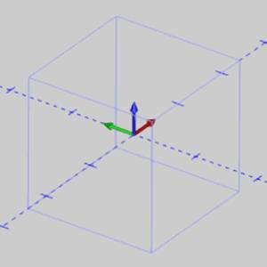
 Wireframe -
The Wireframe View command shows and hides the interior lines
of surfaces and solids.
Wireframe -
The Wireframe View command shows and hides the interior lines
of surfaces and solids. -

-
Blank
- The Blank function is used to hide selected geometry from view, and to prevent that geometry from being affected by any other functions.
To set entities to a blank state, click Blank, select geometry in the graphics
area to add them to the Selected Geometry list, and click OK. The geometry is hidden from view will not be affected by any other functions.
To reverse this state, use Unblank.
-
 Unblank
- The Unblank function is used to remove the blanked state from entities which have previously had that state applied to them using the Blank function. To perform the function, click
Unblank, select the geometry from the list of blanked entities which should have that state removed, and click OK.
Unblank
- The Unblank function is used to remove the blanked state from entities which have previously had that state applied to them using the Blank function. To perform the function, click
Unblank, select the geometry from the list of blanked entities which should have that state removed, and click OK.  Hide All Images -
The Hide All Images function is used to hide any imported
images (in the graphics area) from view. This function is only
available in the View menu. To show the images, click Hide All
Images a second time. This function is used with BobART.
Hide All Images -
The Hide All Images function is used to hide any imported
images (in the graphics area) from view. This function is only
available in the View menu. To show the images, click Hide All
Images a second time. This function is used with BobART. Hide
All Emboss Model - The Hide All Emboss Model
function is used to hide embossed geometry that is created using
BobART. This allows you to view any geometry that is hidden by
the model so it can be selected for other features. To view the
model again, click Hide All Emboss Model a second time.
Hide
All Emboss Model - The Hide All Emboss Model
function is used to hide embossed geometry that is created using
BobART. This allows you to view any geometry that is hidden by
the model so it can be selected for other features. To view the
model again, click Hide All Emboss Model a second time.
- Ortho Projection - The
Ortho Projection function is used to change the view in the graphics
area between the default perspective view and an orthogonal view. To perform the function, you
click Ortho Projection; to return to the default view, click Ortho
Projection a second time.View
an example
-
 Antialiasing
- The Antialiasing function smooths the edges of geometry displayed in the graphics
area. This is only used to improve the appearance
of the geometry in the graphics area, for example, when using
Print Screen to create an image.
Antialiasing
- The Antialiasing function smooths the edges of geometry displayed in the graphics
area. This is only used to improve the appearance
of the geometry in the graphics area, for example, when using
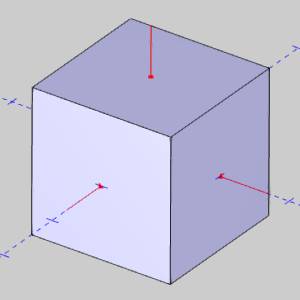
Print Screen to create an image.  Surface Normal - The Surface Normal function is used to
show or hide the surface normals of solids/surfaces in the graphics
area. This indicates the outward (positive) direction of solids/surfaces.
This function is important for creating Multiaxis features. The Reverse Surface Normal Function.View
an example
Surface Normal - The Surface Normal function is used to
show or hide the surface normals of solids/surfaces in the graphics
area. This indicates the outward (positive) direction of solids/surfaces.
This function is important for creating Multiaxis features. The Reverse Surface Normal Function.View
an example
-
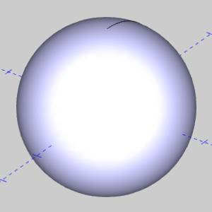
 Shaded
Smooth - The Shading Smooth function is used to smooth
the appearance of solids/surfaces in the graphics area. This is
turned on by default. To turn the function off, click Shading
Smooth. To return to the
default view, click Shading Smooth again.View
an example
Shaded
Smooth - The Shading Smooth function is used to smooth
the appearance of solids/surfaces in the graphics area. This is
turned on by default. To turn the function off, click Shading
Smooth. To return to the
default view, click Shading Smooth again.View
an example
-
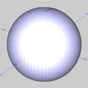
 Polygon
Shaded - The Polygon Shaded function is the default view
used for solid/surface entities. They appear as a shaded solid/surface.
The Polygon Lines function is used to change this view to a triangle
mesh.View
an example
Polygon
Shaded - The Polygon Shaded function is the default view
used for solid/surface entities. They appear as a shaded solid/surface.
The Polygon Lines function is used to change this view to a triangle
mesh.View
an example
-
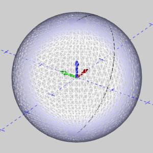
 Polygon
Lines - The Polygon Lines function is used to show the
triangle mesh of solid/surface entities in the graphics area.
When you click Polygon Lines, the view of the solid is updated.
To return to the shaded view, click Polygon Shaded.View
an example
Polygon
Lines - The Polygon Lines function is used to show the
triangle mesh of solid/surface entities in the graphics area.
When you click Polygon Lines, the view of the solid is updated.
To return to the shaded view, click Polygon Shaded.View
an example