


Mill Standard Drilling Example
Introduction
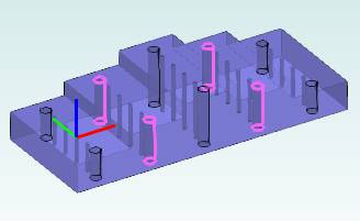
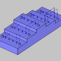
This topic provides an example of how to create standard hole drillingfeatures for milling jobs in BobCAD-CAM.Standard Mill Hole features areused when drilling holes that are parallel to the Z-axis of the machine.This is the most commonly utilized drilling type in BobCAD-CAM.
This tutorial highlights the following functionality of the BobCAD-CAMsoftware:
- Using the Mill Hole Wizard to easily define drilling of more thanone hole size (multiple features) in the initial wizard setup
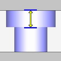
- Using Hole Groups to drill more than one hole depth within a singlehole feature
- Controlling the clearance, rapid, and feed planes between holes
- Using the Machining Strategy to define the types of drilling operationsapplied to the holes
Example File
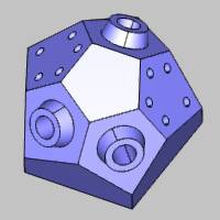
If you are connected to the Internet, the part file for this example can be downloaded automatically by clicking the following link: Mill Standard Drilling Example 1 BBCD
Once you download and saved the zip file, extract the files on your system in an easy place to remember.You can then open the file to use with this tutorial.All files for the tutorials in this help system available for download can be found by clicking on the following link: http://www.bobcad.com/helpfiles.
In theexample file provided, the job, stock, and machine setup are already defined.
Create a Standard Mill Hole Feature
Set the Drilling Type and Select Geometry
-
In the CAMTree, right-click MachineSetup and click Mill DrillHole.
-
In the Mill Hole Wizard, click SelectGeometry.
The Hole Geometry Selection Manager displays. -
Confirm that the default drilling type, Standard Drill, is selected.
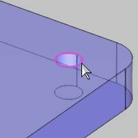
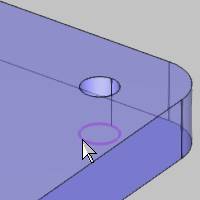
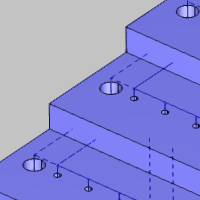
For this example, you can select the cylindricalsurface of each hole directly from the model, but to make selection easier,a separate CAD layer contains a copy of only these surfaces.(Note thatthe Point and Arc Usage options do not apply when selecting cylindricalsurfaces.)
Tip: Weare selecting
-
In the Quick Selection group, of the Home ribbon, click
 Pick By Layer.
 -
In the Select Layer dialog, click Holes.
Click OK.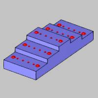
-
Click OK in the SelectionManager.
Geometry selection is finished.Notice the hole list displays eachdiameter hole and its parameters.The software automatically createsa separate Mill Hole feature for each hole diameter.The Depth valuefor both of our hole sizes displays as Multiple.This is due to themultiple depths that are achieved in a single feature using hole groups.The hole depths can be modified in the wizard later, as needed. -
Click Next>> tobegin defining the parameters for the first hole diameter (feature).
Define the Feature Settings for Hole Groups
The Hole Groups table is an important part of the Feature page in theMill Hole Wizard.Each hole group represents a different hole depth, andthe Hole Groups table allows you to preview, break, regroup, rename, andset the parameters for all hole groups in the feature.![]() Click
Click![]() here to expand on the subject of Hole Groups.
here to expand on the subject of Hole Groups.


-
For now, we are using the default MaterialApproach settings.
The Diameteris already properly set from the selected geometry.
The Parametersare also already properly set for this example.
-
Under Hole Groups, clickanywhere in the row of Group 1to select it.
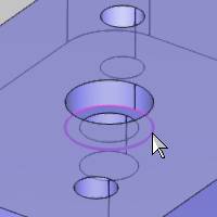
Because the group is now selected, the holegroups preview displays inside the dialog box.
To change the viewing orientation of thepreview, drag the left or middle mouse button to rotate.To pan the preview,press and hold the Ctrl key, anddrag the middle mouse button.To zoom in or out, roll the middle mousebutton forward or backward.
-
In the Hole Groups table, click the name Group1, and type Low.
This hole group is on the lowest level ofthe part, and our custom naming is more descriptive than Group 1.Renaminghole groups is a great way to stay organized when there are many holegroups.
Tip: To edita hole group name, top of feature, or feature depth, click the value (orname) directly in the Hole Groups table.Type the new value or name toupdate it.After editing any value, you can press Tab to move to the nextparameter in the list, or press Enter to finish.
-
Under Hole Groups, clickthe name Group 2.

-
Type Mid to rename Group2.
-
Click the name Group 3,and type High.
We don't make any other changes to the hole groups at this time.Rememberthat we selected cylindrical surfaces so the parameters for the holegroups are automatically set. -
Click Next>>.
Define the Machining Strategy
-
Under Default Strategy,click the Hole machining strategy.
This assigns one center drill operation and one drill operation tothe Current Operations list. -
On the lower left, click Applyto All Features.
The software automatically creates one feature for each hole diameteras seen in the tree on the left.The second feature now uses the sameMachining Strategy as the first. -
Click Next>> three timesto go to the center drill tool data.(No changes are needed for the Machine Sequence orPosting settings.)
Define the Tool Data and Operation Parameters
-
Notice the SystemTool check box is selected.For this example, we use the automaticallyselected system tool information, but be sure to update the tool data,machining data, and feeds and speeds as needed when creating yourown programs.
-
Click Next>>.
Again, we use the default operation parameters, but notice there areno hole groups listed.For center drill and chamfer operations, theparameters defined here are shared across all hole groups.All otheroperation types allow you to define the parameters for each hole groupseparately. -
Click Next>>.
We use System Tool information again for the drill operation, becausethe software automatically loads a tool with the correct diameterfrom the Tool Library.All of the parameters stored with the toolare automatically set in the wizard. -
Click Next>>.
-
Notice the Hole Groups list.Click Low to select it.
Under Cycle Type, click Peck. -
Click the group name Mid,and then select Peck.
Set the Highgroup to Peck using the same process.
Important: Besure to select a hole group before changing any operation parameters,and make sure to set the parameters as needed for all hole groups.
-
Click Next>>.
Define the Second Feature and Compute the Toolpath
-
In the HoleGroups table, repeat the process of selecting the group toview the preview, and then rename each group to Low,Mid, and Highbased on its level on the model.
Again, the hole groups parameters are automatically set because weselected cylindrical surfaces. -
Click Next>>,and notice that the Hole operationtemplate is selected from using Apply to All Features earlier.
-
In the tree on the left, click the last Parameters item.
-
Repeat the process as explained earlier toset all hole groups to the Peckcycle type.
-
On the lower-right, click Compute.
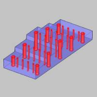
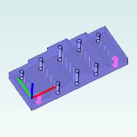
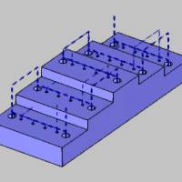
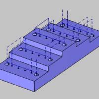
The resulting toolpath is shown next.
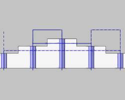
After viewing the toolpath, we see one issue.The rapid plane, applied withinhole groups, is going through the steps of the model because the holeson opposite sides of the part are in the same group.The rapid movementbetween hole groups is determinedby the group retracts as seen in the link moves that retract up abovethe part.Next we modify our hole groups to alleviate the issue.
Edit the Feature, Break and Regroup Holes
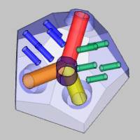
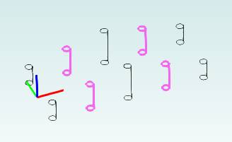
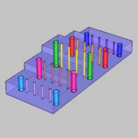
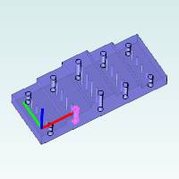
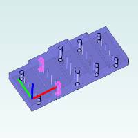
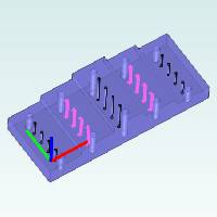
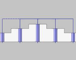
For reference, the following image shows the current hole groups usingone color for each group.Remember that each hole diameter is a singlefeature and we are working with two features (both are shown in the image).
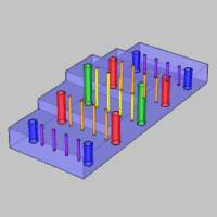
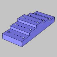
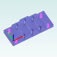
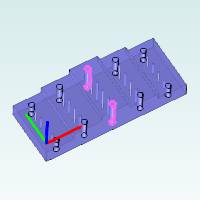
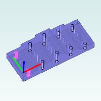
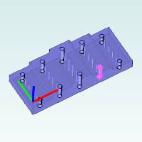
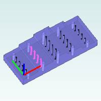
After breaking and regrouping holes in the following steps, the holegroups are as follows (one color for each hole group).This final groupingallows us to optimize the toolpath for both features.
-
In the CAMTree, right-click the first feature name, Feature Mill Hole -
Click the GroupRetracts button under MaterialApproach.
The group retracts handle the rapid movementbetween hole groups, and theyare currently set to a plane in Z with a height of
Close the GroupRetracts dialog box.
Next we modify our hole groups so the groupretracts are used when moving from one step (level) of the model to thenext.
-
Under Hole Groups, clickanywhere in the row of the Lowgroup to select the group and display the preview.
-
With the Low group selected, click BreakHole Group.
The group is separated into four single-hole groups (Low.1 throughLow.4). -
Click anywhere in the row of group Low.1to select it.

Press and hold the Ctrlkey, and click Low.2 to add itto the current selection.
We can see that Low.2 is on the oppositeside of the part so we don't want to regroup these holes.
Tip: You multi-selectitems in the Hole Groups list using the Shift and/or Ctrl keys.Hold Ctrl and click a group to add itto or remove it from the current selection.Hold Shiftand click a group to select all groups between the first and second selections.
Hold the Ctrlkey and select group Low.2 toremove it from the selection.(Click the row of Low.2 in the Number column.)
Press Ctrland click Low.4 to add itto the selection.
We can see that Low.1 and Low.4 are on thesame side of the part, so these are the two holes we want to regroup.
-
With both Low.1 andLow.4 selected, click Regroup Holes.
Click the new group Low.1 to confirm thenew grouping.
-
There are only two holes left on the lower level, so click Low.2, then hold Ctrland click Low.3.
Click RegroupHoles to create a new Low.2 group.
-
Repeat this process of breaking and regrouping holes for themiddle level (group Mid) so that each group only contains the holesthat are on the same side of the part.
There is no need to break the High hole group.
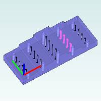
Breakinggroup Mid results in the following groups.
|
Mid.1 |
Mid.2 |
|
|
|
Mid.3 |
Mid.4 |
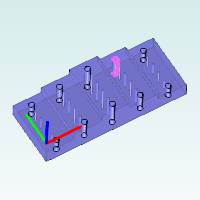
|
|
Groups Mid.1and Mid.4 are regrouped to createa new group, Mid.1.
Groups Mid.2and Mid.3 are regrouped to createa new group, Mid.2.

To update the changes for this feature, clickCompute.
Edit the Second Feature, Break and Regroup Holes
Now we break and regroup the holes for the second feature.Again, theprocess here is to use the Ctrl key to add and remove selections whileviewing the hole groups preview, and then regrouping the holes as needed.In this section we use the Shift modifier to select multiple list items.
- Right-click the second feature name, Feature Mill Hole -
- Under HoleGroups, click anywhere in the row of group Lowto select it.
Press and hold Ctrl,and select group Mid.
With Lowand Mid selected, click Break Hole Group. - Select group Low.1 andobserve the hole groups preview.
Hold Ctrland select Low.2.
Group Low.2 is on the opposite side fromLow.1 and we want to regroup holes that are on the same side of the part.
Hold Ctrland click Low.2 to remove it fromthe selection.
Group Low.3 is also on the opposite sideof the part.
Hold Ctrland click Low.4 to add it to theselection.
We hold Ctrland select all the low level holes that are on the same side of the part:Low.5 and Low.8. - With Low.1, Low.4,Low.5, and Low.8selected, click Regroup Holes.
Click the new Low.1 group to display thepreview.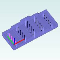
- Click group Low.2.
Press and hold the Shiftkey, and click group Low.7.
Notice that all groups from Low.2 throughLow.7 are selected.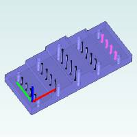
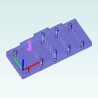
Click RegroupHoles. - Repeat this process to regroup the mid-level holes using thesame process.(Group Mid is regrouped into Mid.1and Mid.2 as shown next.)
- Click Compute to updatethe toolpath.
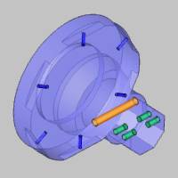
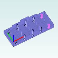
The result of breaking the hole groups isan efficient toolpath for our example part that uses a minimal rapid planewithin groups and only retracts above the part to move from one groupto the next (group retracts).
This concludes the tutorial.